Anti-fatigue impact-resistant pressure relief valve and manufacturing method thereof
A pressure reducing valve, shock-resistant technology, applied in valve devices, engine components, mechanical equipment, etc., to achieve the effect of long life and high reliability
- Summary
- Abstract
- Description
- Claims
- Application Information
AI Technical Summary
Problems solved by technology
Method used
Image
Examples
Embodiment 1
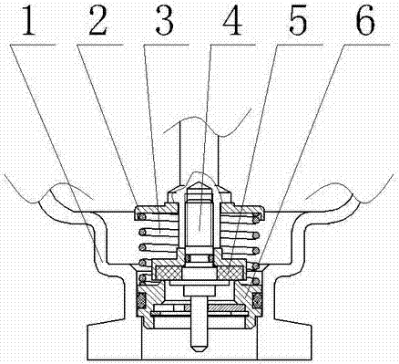
[0022] A method for manufacturing an anti-fatigue and impact-resistant pressure reducing valve, the pressure reducing valve includes a pressure reducing valve main body 1, a pressure seat 2 matching the pressure reducing valve main body 1 and a limit structure 6, an anti-fatigue and impact-resistant spring 3, a piston rod 4 and buffer device 5, wherein the manufacturing method of the used copper wire of spring 3 comprises the following steps:
[0023] 1) Pre-preparation
[0024] ① Use tin phosphor bronze QSn4-4-4 copper billet as the raw material of copper wire;
[0025] ② Select forging equipment equipped with hydraulic generating device, rotary push device and air cooling device; select vacuum resistance furnace as initial forging heating equipment;
[0026] ③Select four forging hammer heads with 90° forging axes in sequence and supporting hydraulic output device as final forging and clamping tooling; then choose ceramic tooling body with tapered inner hole, shock-absorbing...
Embodiment 2
[0036] The whole is consistent with Example 1, the difference is:
[0037] The manufacturing method of the used copper wire of spring 3 comprises the following steps:
[0038] ①The tin phosphor bronze QSn4-4-4 copper blank is heated through a vacuum resistance furnace to a value higher than its theoretical AC 3 At a temperature of 30°C, keep warm for (20d) min / mm according to the diameter of the copper billet, and then take it out of the furnace, and fix the bottom of the copper billet on the rotary push device;
[0039] ②The forging hammer head linked with the rotary push device is pushed by the hydraulic generating device, and the copper billet is extruded into a forging billet with a nearly square cross-section at a feed rate of about 5% for each deformation and a final deformation ratio of 55% to deform the copper billet. The length of one forging deformation of the blank is one forging cycle. After the last forging in one cycle is completed, the forging hammer head is fi...
Embodiment 3
[0044] The whole is consistent with Example 1, the difference is:
[0045] The manufacturing method of the used copper wire of spring 3 comprises the following steps:
[0046] ①The tin phosphor bronze QSn4-4-4 copper blank is heated through a vacuum resistance furnace to a value higher than its theoretical AC 3 At a temperature of 50°C, keep warm for (22d) min / mm according to the diameter of the copper billet, and then take it out of the furnace, and fix the bottom of the copper billet on the rotary push device;
[0047] ②The forging hammer head linked with the rotary push device is pushed by the hydraulic generating device, and the copper billet is extruded into a forging billet with a nearly square cross-section at a feed rate of about 5% for each deformation and a final deformation ratio of 65% to deform the copper billet. The length of one forging deformation of the blank is one forging cycle. After the last forging in one cycle is completed, the forging hammer head is fixe...
PUM
 Abstract
Description
Claims
Application Information
 - R&D
- Intellectual Property
- Life Sciences
- Materials
- Tech Scout
- Unparalleled Data Quality
- Higher Quality Content
- 60% Fewer Hallucinations
Browse by: Latest US Patents, China's latest patents, Technical Efficacy Thesaurus, Application Domain, Technology Topic, Popular Technical Reports.
© 2025 PatSnap. All rights reserved.Legal|Privacy policy|Modern Slavery Act Transparency Statement|Sitemap|About US| Contact US: help@patsnap.com

