Supercharge Your Innovation With Domain-Expert AI Agents!

Machining tool for gear and operation method for machining tool

A gear and tooling technology, applied in gear tooth manufacturing devices, components with teeth, metal processing equipment, etc., can solve the problems of low uniformity of gear grooving depth, low work efficiency, high labor intensity, etc. The effect of labor intensity, improving work efficiency and improving grooving quality

Inactive Publication Date: 2017-11-07
安徽智联管理咨询有限公司
View PDF1 Cites 1 Cited by
  • Summary
  • Abstract
  • Description
  • Claims
  • Application Information

AI Technical Summary

Problems solved by technology

[0003] The purpose of the present invention is to overcome the problems of low working efficiency, poor versatility, high labor intensity and low uniformity of gear grooving depth existing in the grooving process of existing gears, and to provide a gear with good versatility, convenient operation and high working efficiency. Gear processing tooling with high height, wide application range and high uniformity of gear grooving depth and its operation method

Method used


Image

  • Machining tool for gear and operation method for machining tool
  • Machining tool for gear and operation method for machining tool

Examples


Embodiment 1

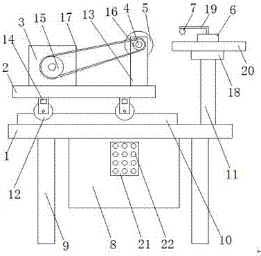
[0020] As attached figure 1 As shown, a gear processing tool includes an operating table 1, a shift plate 2, a motor 3, a rotating shaft 4, a cutting wheel 5, a fastening block 6, an inductor 7 and a control cabinet 8, and it is characterized in that: The operating table 1 is set on the support 9, and the operating table 1 is provided with a guide rail 10, a column 11, the column 11 is provided with a bearing plate 18, and is provided between the bearing plate 18 and the fastening block 6 Gear 20. The shift plate 2 is provided with a walking wheel 12 and a bearing rod 13, and the walking wheel 12 is provided on the guide rail 10. The walking wheel 12 is provided with a driver 14 and the driver 14 is connected to the control The cabinet 8 is connected, the motor 3 is arranged on the shift plate 2, and a driving wheel 15 is arranged on the motor 3, the rotating shaft 4 is arranged on the bearing rod 13, and the rotating shaft 4 is provided with a slave The driving wheel 16, the d...

Embodiment 2

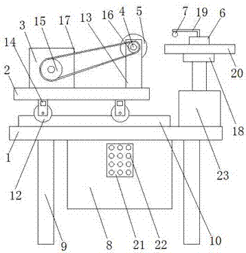
[0027] As attached figure 2 As shown, a gear processing tool includes an operating table 1, a shift plate 2, a motor 3, a rotating shaft 4, a cutting wheel 5, a fastening block 6, an inductor 7 and a control cabinet 8, characterized in that: The operating table 1 is set on the support 9, and the operating table 1 is provided with a guide rail 10, a second motor 23, the second motor 23 is connected to the control cabinet 8, and the second motor 23 is provided with a column 11, the The column 11 is provided with a bearing plate 18, and a gear 20 is arranged between the bearing plate 18 and the fastening block 6. The shift plate 2 is provided with a walking wheel 12, a bearing rod 13, and the walking wheel 12 It is arranged on the guide rail 10, the driving wheel 12 is provided with a driver 14 and the driver 14 is connected to the control cabinet 8, the motor 3 is provided on the shift plate 2, and the motor 3 is provided with a driving wheel 15. The rotating shaft 4 is arrange...


PUM


Abstract

The invention discloses a gear processing tooling, which includes an operation table, a shifting plate, a motor, a rotating shaft, a cutting wheel, a fastening block, an inductor and a control cabinet, and is characterized in that the operation table is arranged on a support , the shifting plate is provided with a traveling wheel and a bearing rod, the motor is arranged on the shifting board, the rotating shaft is arranged on the bearing rod, the driven wheel is connected with the driving wheel through a belt, The cutting wheel is set on the rotating shaft, the fastening block is set on the column, and a bearing frame is set on the fastening block, the sensor is set on the carrying frame, and the control cabinet is set On the operating table, connect the control cabinet with the motor and the sensor. In the present invention, a bearing plate and a fastening block are arranged on the column, and an inductor is arranged on the bearing frame of the fastening block. The stability during the grooving process improves the grooving quality of the gear.

Description

Technical field [0001] The invention relates to the technical field of gear processing, in particular to a gear processing tool and an operation method thereof. Background technique [0002] Gears are toothed mechanical parts that can mesh with each other and are widely used in the mechanical field. The gear teeth directly affect the service life of the gear, and its processing quality directly determines the quality and performance of the gear. For example, the patent application number 201620372711.6 published a new type of gear processing device, which solves the problem of low qualification rate of gear products and decreased output, but it has low work efficiency, poor versatility, high labor intensity, and gear cutting depth. The problem of low uniformity. Summary of the invention [0003] The purpose of the present invention is to overcome the problems of low work efficiency, poor versatility, high labor intensity, and low uniformity of gear grooving depth in the existing...

Claims


Application Information

Patent Timeline
IPC IPC(8): B23F1/00B23F23/04
CPCB23F1/00B23F23/04
Inventor 卢国孝吴义顺
Owner 安徽智联管理咨询有限公司
Features
  • R&D
  • Intellectual Property
  • Life Sciences
  • Materials
  • Tech Scout
  • Unparalleled Data Quality
  • Higher Quality Content
  • 60% Fewer Hallucinations
Learn More