Automatic polaroid storing device for polaroid cleaning

A polarizer, automatic technology, applied in the field of cleaning machinery, can solve the problems of inconsistent vector printing position, poor user experience, insufficient quantity, etc., to achieve the effect of improving satisfaction, quality assurance, and improving work efficiency

Pending Publication Date: 2017-11-07
HANBO HIGH TECH MATERIALS HEFEI CO LTD
3 Cites 5 Cited by

AI-Extracted Technical Summary

Problems solved by technology

[0002] In order to ensure the cleanliness of the polarizer before packaging, the polarizer needs to be cleaned. The traditional cleaning process is as follows: a person manually puts the polarizer at the opening of one end of the polarizer cleaning machine, the polarizer passes through the cleaning machine, and the other two people clean it in the cleaning machine. The film receiving port at the other end manually collects the film. This cleaning process is that the film receiving personnel watch the position of the ...

Method used

Simultaneously, described crossbeam 6 is provided with the main blowing device 17 towards moving cart 2 fronts, and towards the auxiliary blowing device 18 of moving cart 2 sides, described main blowing device 17 is provided with for The fur brush 17a of the overlapping polarizer 27 is peeled off. This is due to the fact that the whole stack of polarizers 27 is stacked together for a long time and there is electrostatic adsorption, which will lead to the fact that when the uppermost one is sucked, the next upper one will be taken up, which will cause poor creases on the taken up polarizers. When the suction nozzle 16 sucks up t...

Abstract

The invention relates to an automatic polaroid storing device for polaroid cleaning. The automatic polaroid storing device comprises a mechanical console, a movable cart, a polaroid cleaning machine and a polaroid collecting device. The movable cart is pushed into a U-shaped area of the mechanical console for fixation after feeding. The mechanical console adsorbs, counts and transfers polaroids to the polaroid cleaning machine for cleaning. The polaroid collecting device screens qualified products and unqualified products after cleaning. The qualified products are stacked on an upper layer and the unqualified products are stacked on a lower layer. According to the automatic polaroid storing device for polaroid cleaning, the operation process is convenient and fast, only one person is required to feed materials and collect the polaroids, only one person is required for feeding and the other person is required for polaroid collection; and manpower is saved, time cost is reduced, working efficiency is improved, the quality of obtained polaroid products is guaranteed, and the degree of satisfaction of customers is increased.

Application Domain

Technology Topic

Image

  • Automatic polaroid storing device for polaroid cleaning
  • Automatic polaroid storing device for polaroid cleaning
  • Automatic polaroid storing device for polaroid cleaning

Examples

  • Experimental program(1)

Example Embodiment

[0022] The present invention will be further described below in conjunction with accompanying drawing:
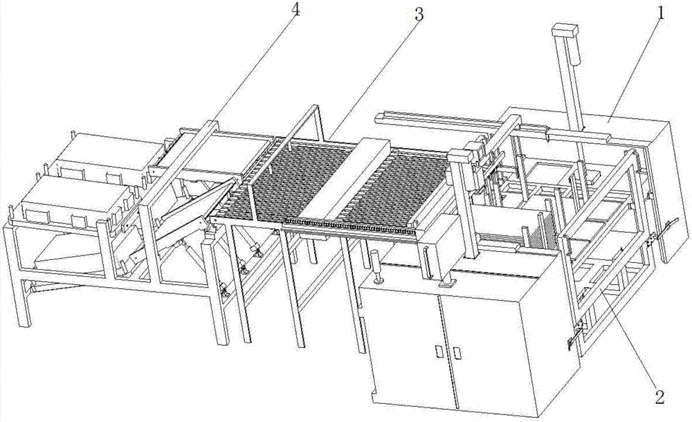
[0023] refer to figure 1 The shown automatic polarizer cleaning device includes a mechanical console 1 , a moving trolley 2 , a polarizer cleaning machine 3 and a film receiving device 4 .
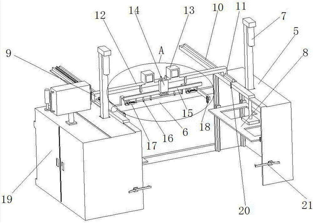
[0024] refer to figure 2 As shown, an electrical control cabinet 19 is provided on one side of the mechanical console 1, and the mechanical console 1 includes two symmetrically arranged racks 5, and the two racks 5 are connected by cross beams 6 to accommodate mobile In the U-shaped area of ​​the trolley 2, the first lifting platform 8 driven by the lifting motor 7 is arranged on the two frames 5 . The frame 5 is provided with a positioning pin 21 for fixing the mobile trolley 2 , and the mobile trolley 2 is correspondingly provided with a plug plate 23 matching with the positioning pin 21 .
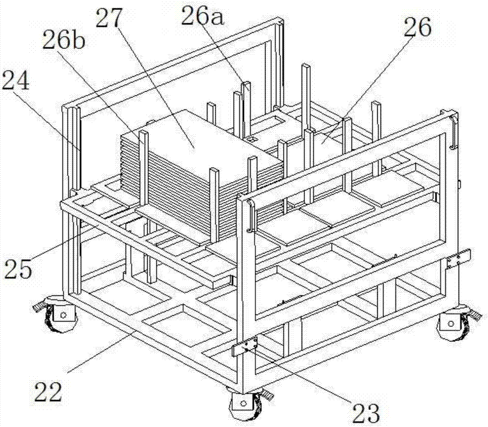
[0025] refer to image 3 As shown, the mobile cart 2 includes a car body 22, and the car body 22 is provided with four vertical guide rails 24, and the four vertical guide rails 24 are jointly movably connected with a second lifting platform 25, and the second lifting platform Two polarizer placement areas 26 are arranged on the platform 25 . The periphery of each polarizer placement area 26 is provided with six columns for limiting the polarizer 27, wherein one column 26a runs through the second lifting platform 25 and is connected to the bottom of the car body 22, and the other five columns 26b are connected to the second lifting platform 25. The platform 25 is movably connected, and can be adjusted forward and backward, and is conveniently compatible with the placement of polarizers 27 of different sizes.
[0026] refer to Figure 4 As shown, when the mobile trolley 2 enters the U-shaped area, the positioning bolt 21 is connected with the flashing plate 23 to fix the mobile trolley 2, and the two first lifting platforms 8 extend into the two protruding ends of the second lifting platform 25 respectively. Below, the second lifting platform 25 can move up and down along with the first lifting platform 8 to send the polarizer 27 to a suitable position to be transferred.
[0027] The two frames are respectively provided with an inductor 20 for sensing the stacking height of the polarizer 27 on the mobile trolley 2, and the height of the inductor 20 is fixed at a suitable position (according to the descending height range of the suction nozzle 16 and the second lifting platform 25) when starting work. The entire stack of polarizers 27 on the mobile cart 2 moves from bottom to top, and when the sensor 20 senses the position of the uppermost layer of the entire stack of polarizers, the entire stack of polarizers stops moving and waits for transfer.
[0028] refer to figure 2 and Figure 7 As shown, one of the frame 5 is provided with a screw slide 9 driven by a servo motor, and the other frame 5 is correspondingly provided with a transplanting guide rail 10 and is movably connected with the transplanting guide rail 10. A slide block 11, a transplanting beam 12 is connected between the slide block 11 and the slide table of the screw mandrel slide table 9, and the transplanting beam 12 is provided with two counters 13 and a lifting cylinder 14, and the lifting cylinder 14 The piston rod end of the piston rod is vertically downward and is fixed with a small beam 15 at the piston rod end, and eight vertically downward suction nozzles 16 (each four on the left and right sides) are evenly distributed on the small beam 15 .
[0029] After the whole stack of polarizers 27 on the mobile trolley 2 stopped moving upwards, the polarizers 27 just stopped under the suction nozzle 16. At this time, the upgrade cylinder 14 can be lowered by electrical control and the suction nozzle 16 will absorb the polarizer 27 at the same time. The guide rail of the screw slide table 9 and the transplanting guide rail 10 extend above the entry end of the conveyor belt 28 of the polarizer cleaning machine 3 .
[0030] At the same time, the beam 6 is provided with a main air blowing device 17 facing the front of the mobile cart 2, and an auxiliary air blowing device 18 facing the side of the mobile cart 2. The brush 17a of the sheet 27. This is due to the fact that the whole stack of polarizers 27 is stacked together for a long time and there is electrostatic adsorption, which will lead to the fact that when the uppermost one is sucked, the next upper one will be taken up, which will cause poor creases on the taken up polarizers. When the suction nozzle 16 sucks up the sheet, the main air blowing device 17 and the auxiliary air blowing device 18 continuously blow air to the front and side of the stacked polarizer 27 respectively, blowing the entire stack of polarizers away, and avoiding the two sheets being adsorbed together and being sucked. and the front end of the main air blowing device 17 is provided with a brush 17a, and the edge of the polarizer 27 needs to move upward through the brush 17a during the rising process, and the overlapping polarizer 27 that is brought up is swept away by the bendable characteristics of the brush 17a. Falling, to further prevent the lamination phenomenon.
[0031] The polarizer cleaning machine 3 is arranged between the mechanical console 1 and the film receiving device 4, the polarizer cleaning machine 3 is an existing equipment, refer to Figure 5 The shown polarizer cleaning machine 3 is equipped with a CCD detector 29 and a thickness detector 30; both the CCD detector 29 and the thickness detector 30 are purchased equipment, and the CCD detector 29 is mainly responsible for detecting the color of the polarizer 27, Bad situations such as the pattern of the arrow, no arrow, and the reversal of the arrow; the thickness detector 30 is to further prevent the bad situation caused by the two polarizers 27 being adsorbed together.
[0032] refer to Image 6 As shown, the film receiving device 4 includes a film receiving transition platform and a double-layer film receiving frame. The film receiving transition platform is a movable platform 31 driven by a cylinder 32. One end of the movable platform 31 is connected to the polarizer cleaning machine 3 The delivery ends of the conveyor belt 28 are connected; the double-deck receiving racks include qualified sheet racks 33 positioned on the upper floor arranged in the horizontal direction, and unqualified sheet racks 34 arranged upwardly inclined on the lower floor; Detector 29 and thickness detector 30 detect qualified sheets, and the piston rod of cylinder 32 is extended normally. At this time, movable platform 31 remains horizontal and is on the same plane as conveyor belt 28 of polarizer cleaning machine 3. Polarizer cleaning machine 3 The sent polarizer 27 enters the qualified sheet rack 33 through the movable platform 31 .
[0033]For the unqualified sheets detected by the CCD detector 29 and the thickness detector 30, the piston rod of the cylinder 32 shrinks, and the movable platform 31 tilts downward about 60 degrees to be opposite to the inclination of the unqualified sheet frame 34. At this time, the polarizer is clean. The polarizer 27 that machine 3 sends then enters unqualified sheet material frame 34 by movable platform 31.
[0034] Working process of the present invention is as follows:
[0035] Firstly, stack polarizers 27 in the polarizer placement area 26 on the mobile cart 2, then push the mobile cart 2 into the U-shaped area, and the left and right sides of the second lifting platform 25 on the mobile cart 2 are convex. Out part is just placed on the first elevating platform 8 of both sides, and positioning latch 21 is connected with flashboard 23 and fixes mobile trolley 2, starts operation.
[0036] The lifting motor 7 drives the first lifting platform 8 to move upward, thereby driving the second lifting platform 25 to rise, and when the uppermost polarizer 27 rises to the sensor 20, it stops rising; at this time, the uppermost polarizer 27 is located at the suction nozzle 16 Below, the upgrade cylinder 14 moves to make the suction nozzle 16 drop to absorb the uppermost polarizer 27. During the adsorption process, the main air blowing device 17 and the auxiliary air blowing device 18 continuously blow air to the front and side of the stacked polarizer 27 respectively. Blow off the whole stack of polarizers to prevent the two pieces from being sucked together; at the same time, the brush 17a plays the role of peeling off the overlapped polarizers.
[0037] After the adsorption, the lifting cylinder 14 moves to make the polarizer 27 rise, and then the servo motor rotates to drive the screw slide table 9 to move forward, and the adsorbed polarizer 27 is transported to the inlet end of the conveyor belt 28 of the polarizer cleaning machine 3, and then the 14 cylinder is lifted Descend to place the polarizer 27 on the conveyor belt 28, then reset the suction nozzle 16 and other components, and repeat this until all the stack of polarizers 27 on the moving trolley 2 is transferred to the polarizer cleaner 3.
[0038] Since the entire stack of polarizers on the mobile cart 2 sucks one piece, there will be one less piece, so that after a certain degree, the suction nozzle will not touch the polarizer. To solve this problem, software and electrical control can be used to set every 5 pieces Polarizers, the first lift platform 8 is raised upwards by the thickness of 5 polarizers; at the same time, a hole can be opened at the corresponding position on the second lift platform 25 and the sensor 20, and when the whole stack of polarizers is sucked, the sensor 20 When it is sensed that there is an opening below, the entire mechanical console 1 automatically transplants the polarizer 27, and the second lifting platform 25 of the mobile cart 2 drops to the lowest position and enters the state to be loaded.
[0039] In the process of transplanting the polarizer 27, every time a piece of polarizer 27 is absorbed, the counter 13 counts 1, and so on, when the two counters 13 count up to 200 at the same time, the mechanical console 1 stops putting the film; When it is full of 200 and the other side is less than 200, the side that is full of 200 will stop sucking tablets first, and the side that is less than 200 will continue to suck tablets until the machine stops when both sides are full of 200. , continue to start counting from 0, and the counting numbers are synchronously displayed on the display on the electrical control cabinet 19, which is convenient for the feeding personnel to control.
[0040] The polarizer 27 transferred to the polarizer cleaning machine 3 is detected by the CCD detector 29 and the thickness detector 30, and the unqualified sheet is sent to the lower unqualified sheet rack 34 through the degree platform, and the qualified sheet is sent into the For the qualified sheet material rack 33 on the upper floor, the staff can recycle according to the corresponding category.
[0041] The above-mentioned embodiments are only descriptions of preferred implementations of the present invention, and are not intended to limit the scope of the present invention. Variations and improvements should fall within the scope of protection defined by the claims of the present invention.

PUM

no PUM

Description & Claims & Application Information

We can also present the details of the Description, Claims and Application information to help users get a comprehensive understanding of the technical details of the patent, such as background art, summary of invention, brief description of drawings, description of embodiments, and other original content. On the other hand, users can also determine the specific scope of protection of the technology through the list of claims; as well as understand the changes in the life cycle of the technology with the presentation of the patent timeline. Login to view more.

Similar technology patents

Headphone apparatus

InactiveUS20060104471A1Easy to changeEasy to operateHeadphones for stereophonic communicationSupra/circum aural earpiecesAcoustic propertyEngineering
Owner:SONY CORP

Classification and recommendation of technical efficacy words

  • Save manpower and time cost
  • Easy to operate
Why Eureka
Try Eureka