
Bilateral underwater undercurrent collision concentrated energy dissipater

A technology of energy dissipation and subsurface flow, which is applied in water conservancy projects, sea area engineering, coastline protection, etc., to achieve the effects of protecting facilities, improving quality, and high energy dissipation rate

Pending Publication Date: 2017-11-07
POWERCHINA CHENGDU ENG
View PDF8 Cites 1 Cited by
  • Summary
  • Abstract
  • Description
  • Claims
  • Application Information

AI Technical Summary

Problems solved by technology

[0005] Therefore, the current structural design has not yet made full use of the water tongues on both sides to collide and frictionally dissipate energy

Method used


Image

  • Bilateral underwater undercurrent collision concentrated energy dissipater
  • Bilateral underwater undercurrent collision concentrated energy dissipater
  • Bilateral underwater undercurrent collision concentrated energy dissipater

Examples


Embodiment Construction

[0019] The present invention will be further described below in conjunction with the accompanying drawings.

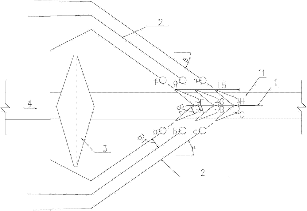
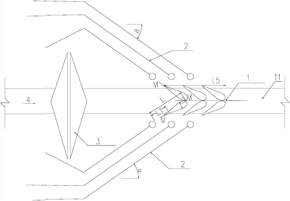
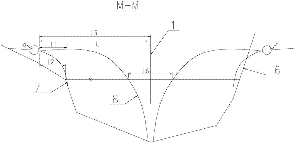
[0020] Such as figure 1 , figure 2 , image 3 The shown double-sided underwater submerged flow collision concentrated energy dissipator includes a downstream channel 11, at least one bank release structure 2 is arranged on the side of the downstream channel 11, and at least one bank release structure 2 is provided with The outlet (a) of the bank release structure, the water tongue (A) originating from the bank release structure outlet (a) realizes energy dissipation in the downstream channel 11, wherein the water tongue outer edge 8 of each water tongue (A) The point of intersection with the bottom of the downstream channel 11 is located on this side of the central line 1 of the channel.

[0021] In the field of the present invention, "energy dissipater" refers to: eliminate the excess kinetic energy of the rapid discharge of the drainage structure or the drop stru...


PUM


Abstract

The invention relates to the water conservancy and hydropower industry, in particular to a bilateral underwater undercurrent collision concentrated energy dissipater capable of effectively reducing the transverse velocity component, reducing the transverse impact force of nappes on bank slopes and improving the river channel revetment safety guaranteeing performance. The energy dissipater comprises a downstream river channel; at least one side discharge building is arranged on the sides of the downstream river channel; at least one side discharge building outlet is formed in each side discharge building; the nappes coming from the side discharge building outlets are subjected to energy dissipation in the downstream river channel; and the intersection of the outer nappe edge of each nappe and the bottom of the downstream river channel is located on the side of the midstream of the river channel. With the energy dissipater, the energy and structure distribution of water flows is utilized ingeniously, so that facilities are well protected while energy dissipation is guaranteed, and the energy dissipater is particularly applicable to various flood discharging tunnel energy dissipaters.

Description

technical field [0001] The invention relates to the water conservancy and hydropower industry, in particular to a double-sided underwater undercurrent collision concentrated energy dissipator. Background technique [0002] With the country's demand for hydropower and clean energy, a large number of high dams have been built to generate electricity using water heads. Due to the large flow during the flood season, some water bodies need to be vented downstream through flood discharge structures. At present, the flood discharge structures are mainly composed of dam body flood discharge and bank flood discharge structures. The outlet of the bank flood discharge structure is located downstream of the dam, and is generally discharged into the downstream channel by deflecting flow. The flood discharge structure outlet can be arranged on one side or both sides. [0003] The flood discharge outlets arranged on one side are generally arranged in sequence in order to avoid the concent...

Claims


Application Information

Patent Timeline
IPC IPC(8): E02B8/06
CPCE02B8/06
Inventor 杨敬王仁坤夏勇沈文莉石江涛
Owner POWERCHINA CHENGDU ENG
Learn More