
Circulation cooling type micro-coring drill bit

A technology for circulating cooling and coring drill bits, which is applied to drill bits, drilling equipment, earthwork drilling and mining, etc. It can solve the problems of high mechanical load, large thermal load, difficulty in forming micro-cores, and high labor intensity of drill bits, so as to improve core quality. quality, avoid crushing and re-crushing, improve integrity and core yield

Inactive Publication Date: 2017-11-07
弘毅天承知识产权股份有限公司
View PDF0 Cites 5 Cited by
  • Summary
  • Abstract
  • Description
  • Claims
  • Application Information

AI Technical Summary

Problems solved by technology

The micro-core at the core is difficult to quickly move out from the center of the drill bit under the action of diffuse flow or eddy current, which will cause the micro-core to be squeezed and broken again under the action of the drill bit’s continuous downward drilling, making it difficult to form a complete micro core
At the same time, during the rotary drilling process of the drill bit, the blade scrapes and cuts the rock at the bottom of the well, and continuously produces cuttings. Well wall) constantly collides at high speed, and at the same time the bottom of the well (or well wall) is squeezed and scraped by the blade; therefore, the technical problem that still exists in the prior art is: High-speed collision, rapid wear of the blade, high mechanical load and high thermal load, and labor-intensive replacement of the drill bit

Method used


Image

  • Circulation cooling type micro-coring drill bit
  • Circulation cooling type micro-coring drill bit

Examples


Embodiment 1

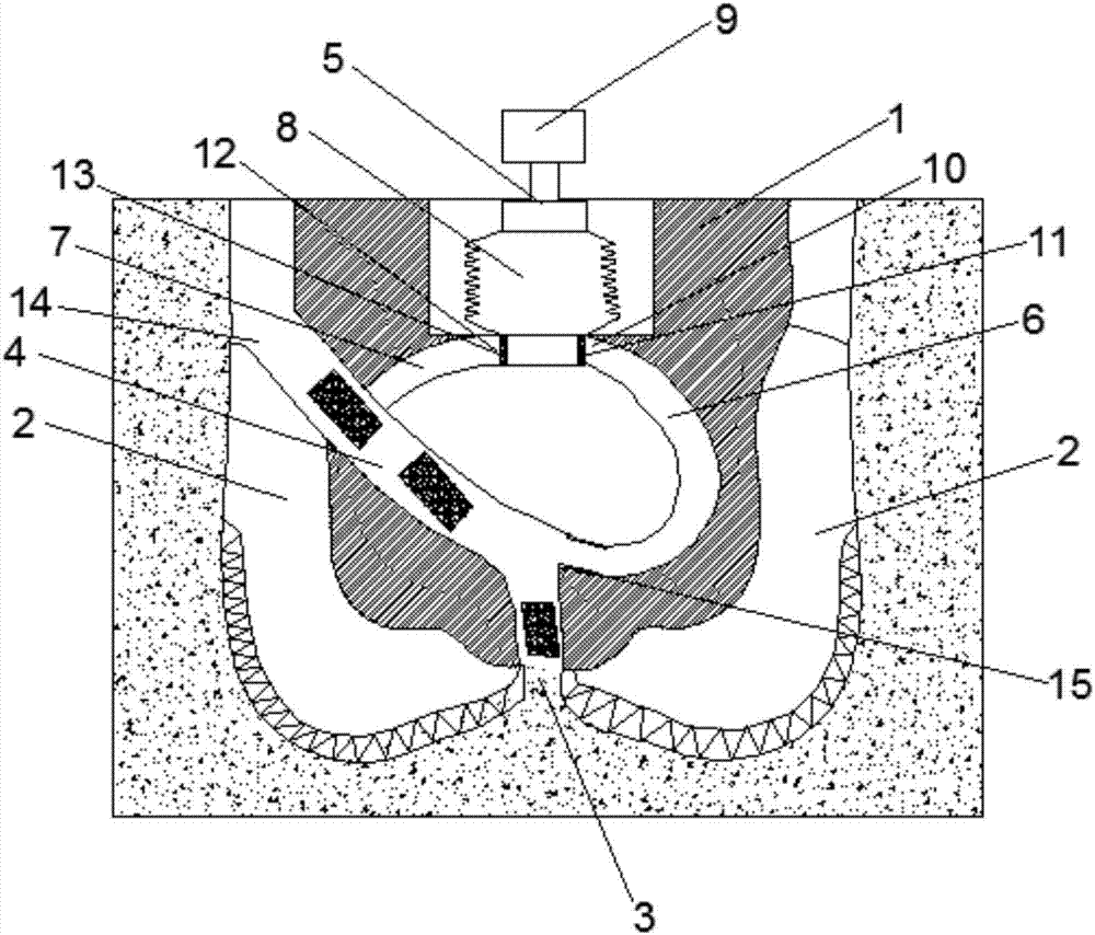
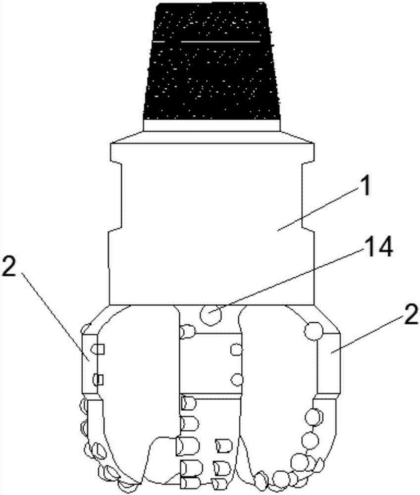
[0028] Such as figure 1 and figure 2As shown, the present embodiment provides a circulating cooling type micro core drill, comprising a drill body 1 and a blade 2 arranged on the drill body 1, a core hole 3 is provided in the middle of the bottom end of the drill body 1, and a core hole 3 is provided in the drill body 1. The top of the core hole 3 is provided with at least one coring passage 4 communicated with the coring hole 3, the lower end of the coring passage 4 communicates with the coring hole 3, and the port at the upper end of the coring passage 4 is a core outlet 14, and the coring The channel 4 has the same diameter as the coring hole 3, which is 13-23mm; the drill bit body 1 is also provided with a circulating cooling channel and a cooling device 5 communicating with the coring channel 4, specifically, the circulating cooling channel includes an output channel 6 and a pumping The suction channel 7 and the cooling device 5 include a stretching cylinder 8 and a hyd...


PUM

PropertyMeasurementUnit
Angleaaaaaaaaaa

Abstract

The invention provides a circulating cooling micro core drill bit, which comprises a drill body, a blade arranged on the drill body and a core hole arranged at the end of the drill body, and at least one coring hole is arranged in the drill body. Coring passage communicated, the drill body is also provided with a circulating cooling passage and a cooling device connected with the coring passage, the circulating cooling passage includes an output passage and a suction passage, and the cooling device includes a stretching cylinder and a driving extension filled with cooling liquid. The hydraulic cylinder compressed by the pressure cylinder is provided with an output port and an output valve corresponding to the output channel and a suction port and a suction valve corresponding to the suction channel in the stretching cylinder, and the cooling liquid in the stretching cylinder flows in through the output channel To the coring channel, and then return to the stretching cylinder through the suction channel. By implementing the technical solution, it is possible to effectively absorb a large amount of heat generated during the drilling process of the drill bit, reduce the heat load of the drill bit, and effectively improve the integrity and core formation rate of the micro-rock core to form a standard micro-rock core.

Description

technical field [0001] The invention relates to the technical field of drilling tools, in particular to a circulating cooling micro core drill bit. Background technique [0002] In petroleum and geological exploration, in order to understand the geological conditions of the formation, it is necessary to take rock samples from the drilled formation to determine the mineral composition in the formation and the geological analysis of the rock property parameters of the formation. The quality and recovery rate of core samples will directly affect the accuracy of geological analysis. [0003] At present, the drilling fluid injection holes of the micro-coring bit are all arranged around the core of the drill bit. Since the surrounding drilling fluid injection holes are all injecting high-speed fluid to the bottom of the well at the same time, the injection holes form a diffuse flow or even a vortex toward the center of the drill bit. The micro-core at the core is difficult to qui...

Claims


Application Information

Patent Timeline
IPC IPC(8): E21B10/60E21B25/00
CPCE21B10/602E21B10/605E21B25/00
Inventor 赵红昌陈伊苒
Owner 弘毅天承知识产权股份有限公司
Learn More