Annulus-pressurizing well cementing device

A cementing and annulus technology, applied in the direction of wellbore/well components, earthwork drilling, sealing/isolation, etc., can solve the problems of cement slurry leakage pressure, cement slurry weight loss, poor isolation quality, etc., to improve solid The effects of well pressure, pressure stability after cementing and simple structure

Pending Publication Date: 2017-11-07
YANGZHOU CHENGCHUANG GASOLINEEUM MACHINERY
View PDF6 Cites 2 Cited by
  • Summary
  • Abstract
  • Description
  • Claims
  • Application Information

AI Technical Summary

Problems solved by technology

[0002] For the development of oil fields, due to the influence of various factors, the underground situation has become quite complicated. At this time, the difficulty of cementing is becoming more and more difficult, and the quality requirements for cementing are also getting higher and higher. However, in the process of work, Due to the high pressure and low permeability and the short stoppage time of water injection wells, the cement slurry loses weight after cementing and cementing, resulting in poor isolation quality and technical problems of cement slurry leakage pressure

Method used


Image

  • Annulus-pressurizing well cementing device

Examples


Embodiment

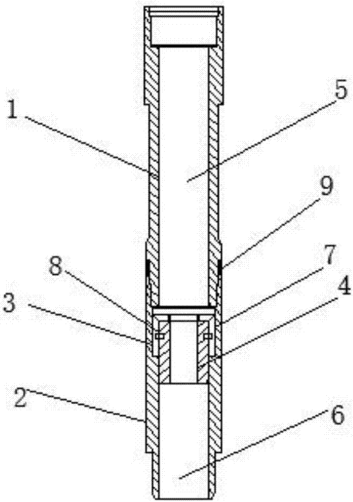
[0029] Such as figure 1 An annulus pressurized well cementing device shown includes an upper joint 1, a lower joint 2, a fixed sleeve 3 and a sliding sleeve 4, the upper joint 1 is installed above the lower joint 2, and the upper joint 1 is provided with a second A cavity 5, a second cavity 6 is arranged inside the lower joint 2, the first cavity 5 corresponds to the second cavity 6, and a fixing sleeve 3 is arranged inside the second cavity 6, so A sliding sleeve 4 is arranged inside the fixed sleeve 3 .

[0030] Wherein, the inner wall of the upper end of the second cavity 6 is provided with a groove 7, and the fixing sleeve 3 is arranged inside the groove 7;

[0031] When in use, the fixed sleeve 3 is placed through the groove 7 provided, so that the sliding sleeve 4 can closely fit with the inside of the second cavity 6 to ensure the reliability of the sliding sleeve and facilitate subsequent pressurization.

[0032] Wherein, it also includes a shear pin 8 arranged betwe...


PUM


Abstract

The invention relates to an annulus-pressurizing well cementing device. The annulus-pressurizing well cementing device comprises an upper connector, a lower connector, a fixed sleeve and a sliding sleeve, wherein the upper connector is installed on the upper portion of the lower connector, a first cavity is formed in the upper connector, a second cavity is formed in the lower connector, and the first cavity and the second cavity correspond to each other; and the fixed sleeve is arranged in the second cavity, and the sliding sleeve is arranged on the inner side of the fixed sleeve. The annulus-pressurizing well cementing device is simple in structure, convenient to use and capable of enhancing well cementing quality effectively.

Description

technical field [0001] The invention relates to the technical field of petroleum machinery, in particular to an annular pressurized well cementing device. Background technique [0002] For the development of oil fields, due to the influence of various factors, the underground situation has become quite complicated. At this time, the difficulty of cementing is becoming more and more difficult, and the quality requirements for cementing are also getting higher and higher. However, in the process of work, Due to the high pressure and low permeability and the short stoppage time of the injection well, the cement slurry loses weight after cementing, resulting in poor isolation quality and the technical problems of cement slurry leakage pressure. Contents of the invention [0003] The purpose of the present invention is to provide an annulus pressurized well cementing device, which solves the technical problem of leakage pressure in the prior art; [0004] The technical scheme ...

Claims


Application Information

Patent Timeline
Patent Type & Authority Applications(China)
IPC IPC(8): E21B33/13
CPCE21B33/13
Inventor 高大军崔鸿全
Owner YANGZHOU CHENGCHUANG GASOLINEEUM MACHINERY
Why Eureka
Try Eureka