Efficient heat exchange pipe, heat exchanger with heat exchange pipe and air conditioner

A heat exchange tube and heat exchanger technology, which is applied in the fields of high-efficiency heat exchange tubes and heat exchangers and air conditioners with the heat exchange tubes, can solve the problem of reducing blasting strength, reducing the energy efficiency ratio of air conditioners, and reducing the flow rate of small U-bends and other problems, to achieve the effect of improving heat exchange efficiency, realizing energy saving and environmental protection, and high heat exchange efficiency

Inactive Publication Date: 2017-11-07
刘晓瀚 +1
View PDF6 Cites 1 Cited by
  • Summary
  • Abstract
  • Description
  • Claims
  • Application Information

AI Technical Summary

Problems solved by technology

[0003] The heat exchange tube is composed of a long tube and a small U-bend welded at one or both ends of the long tube. Due to the shielding of the side plates and fins, the welding torch can only use a top-down angle to check the length of the long tube and the small U-bend. The connection is welded, and the connection between the two cannot be welded from a bottom-up angle
Therefore, in the prior art, it is impossible to weld the long pipe into the small U-bend at all, and only the connection method of inserting the small U-bend into the long pipe can be used.
[0004] In order to adapt to the development of small inner diameter, it is necessary to limit the inner diameter of the long pipe to less than 7mm, and to realize the insertion of the elbow into the long pipe, the diameter of the small U-bend needs to be set smaller, so that the flow rate of the small U-bend Reduced, the resistance of the medium flowing in the small U-bend is very large, especia

Method used


Image

  • Efficient heat exchange pipe, heat exchanger with heat exchange pipe and air conditioner
  • Efficient heat exchange pipe, heat exchanger with heat exchange pipe and air conditioner
  • Efficient heat exchange pipe, heat exchanger with heat exchange pipe and air conditioner

Examples


Embodiment 2

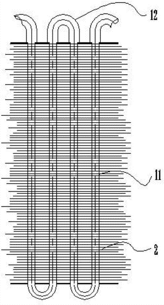
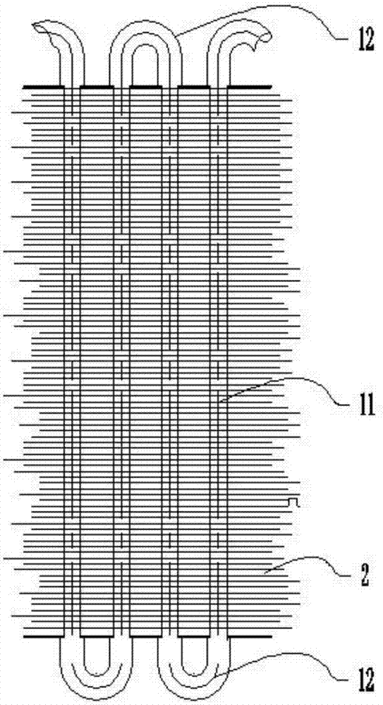
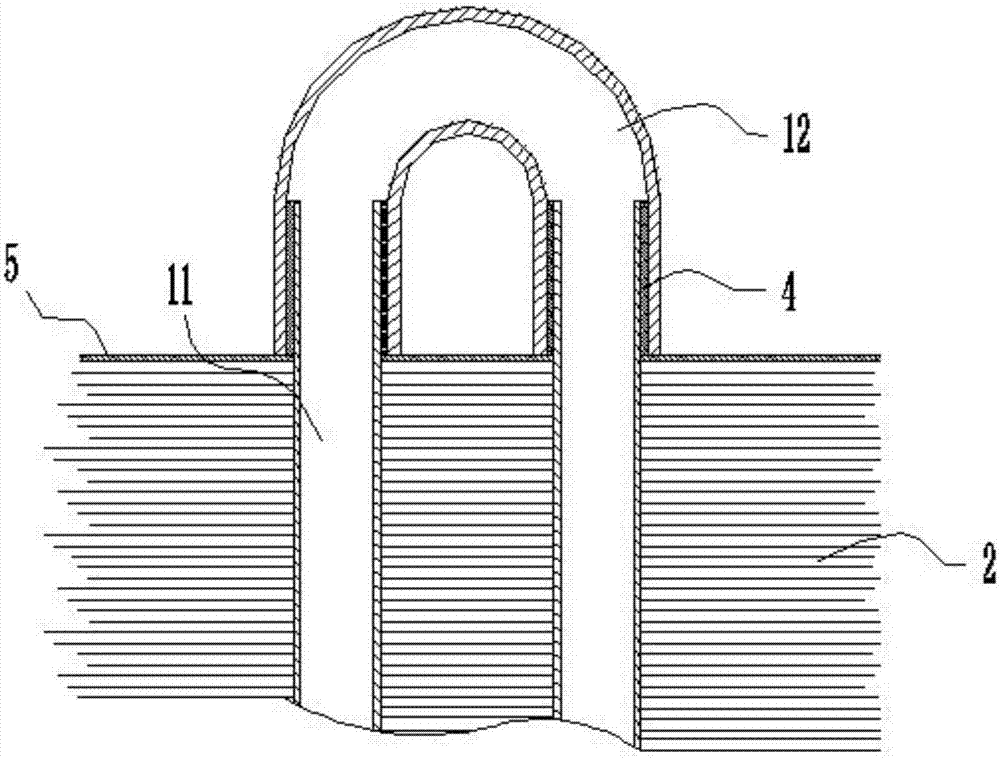
[0054] A heat exchange tube, such as Figure 16-21 As shown, the difference between this embodiment and the embodiment is that the heat exchange tube in this embodiment is not a round tube but a flat tube body; the equivalent diameter of the inner diameter of a single hole of the tube body is less than 7mm; when the tube body is not When there is a partition, its equivalent diameter is less than 7mm, preferably less than 5mm; when there is a partition in the pipe body, the pipe body will be divided into multiple passages, and the single hole refers to the passage here; because the pipe body is small , so that the distance between the tubes can be reduced, so that the efficiency of the fins is improved, the effective area of ​​heat transfer is increased, the flow resistance when the air flows through is reduced, the heat exchange efficiency is improved, and the work efficiency is high.

[0055] Such as Figure 4 , 6 As shown, a heat exchanger, the heat exchanger includes a he...


PUM

PropertyMeasurementUnit
Diameteraaaaaaaaaa
Equivalent diameteraaaaaaaaaa

Abstract

The invention discloses an efficient heat exchange pipe. The efficient heat exchange pipe comprises a main pipe, fins matched with the main pipe, and an end pipe at least arranged at one end of the main pipe. The end portion of the end pipe is provided with an edge wrapping section wrapping the outer surface of the main pipe part. The outer surface of the main pipe and the inner surface of the edge wrapping section are in seal fit through welding flux. The equivalent diameter of the inner diameter of a single hole of the main pipe is smaller than 7 mm, and at least one protruding tooth is arranged on the inner wall of the main pipe. According to the efficient heat exchange pipe, the connecting manner that the main pipe is inserted in the end pipe is adopted so that the pipe diameter of the main pipe can be set to be small, the pipe wall of the end pipe can be thickened, the strength of the heat exchange pipe is enhanced, meanwhile, the heat exchange efficiency is improved, the safety performance of the heat exchange pipe is good, and the heat exchange effect is high. Connection is achieved through the welding flux, the overall strength of the heat exchange pipe cannot be influenced, the welding position is not prone to leakage, and the service life of the heat exchange pipe is long. Through the arrangement of the high protruding teeth, the purpose of good heat transfer between media and a pipe body is achieved, and the heat exchange efficiency is extremely high.

Description

technical field [0001] The invention belongs to the technical field of air-conditioning heat exchange, and in particular relates to a high-efficiency heat exchange tube, a heat exchanger and an air conditioner provided with the heat exchange tube. Background technique [0002] With the rise of raw materials such as copper prices and the country's requirements for air-conditioning energy efficiency, copper tubes are developing in the direction of thinner diameters. With the setting of small inner diameters of copper tubes, when the overall structural size of the heat exchanger remains unchanged, the relationship between tubes and tubes The distance between them can be reduced, so that the efficiency of the fins is improved, the effective area of ​​heat transfer is increased, and the flow resistance when the air flows through is reduced. At the same time, the reduction of the inner diameter of the tube can increase the Re number of the fluid in the tube and increase the heat t...

Claims


Application Information

Patent Timeline
IPC IPC(8): F28D1/047F28F1/42
CPCF28D1/0477F28F1/42
Inventor 李丽辉刘晓瀚
Owner 刘晓瀚
Why Eureka
Try Eureka