A thermal shock assessment test platform for lateral rotation of specimens

A technology of test testing and thermal shock, applied in the testing of machines/structural components, measuring devices, instruments, etc., can solve the problems of long test preparation time, unstable test bench structure, inconvenient temperature measurement, etc., and achieve work efficiency High, saving test costs, shortening the effect of test preparation time

Active Publication Date: 2019-05-14
KUNMING UNIV OF SCI & TECH
View PDF6 Cites 0 Cited by
  • Summary
  • Abstract
  • Description
  • Claims
  • Application Information

AI Technical Summary

Problems solved by technology

[0004] The technical problem to be solved by the present invention is: the present invention provides a thermal shock assessment test platform for lateral rotation of the test piece. Only one group can be tested during the research, and the existing test bench structure is unstable, not compact, inconvenient for temperature measurement, long test preparation time, complicated process, etc.

Method used


Image

  • A thermal shock assessment test platform for lateral rotation of specimens

Examples


Embodiment 1

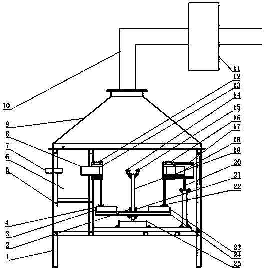
[0024] Embodiment 1: as figure 1 As shown in the figure, a thermal shock assessment test platform for the lateral rotation of the test piece includes a test bench support 1, a position sensor II2, a position sensor I3, a linear cylinder I4, a heat preservation chamber 6, a fixture I12, an infrared thermometer I14, an infrared measuring instrument Thermometer II15, fixture II16, cooler 17, straight rod I19, straight rod II20, position sensor III21, linear cylinder II22, position sensor IV23, guide rail 24, swing cylinder 25; the test bench support 1 is equipped with a heat preservation chamber 6 , the fixture I12 and the fixture II16 clamp the test piece I8 and the test piece II18 respectively, the fixture I12 and the fixture II16 are connected to the linear cylinder I4 and the linear cylinder II22 through the connecting rod, the straight rod I19 is installed on the guide rail 24, and the top of the straight rod I19 The infrared thermometer I14 and the infrared thermometer II15...

Embodiment 2

[0025] Embodiment 2: as figure 1As shown, a thermal shock assessment test platform for test piece laterally rotating, this embodiment is the same as Example 1, wherein a smoke hood 9 is installed on the upper part of the assessment test platform, and the smoke hood 9 is connected to the smoke exhaust pipe 10, and the smoke exhaust pipe 10 is connected A high-temperature duct exhaust fan 11 is installed on the smoke pipe 10 . The hot air inside the test bench can be extracted to ensure that the position sensor II2, position sensor I3, infrared thermometer I14, infrared thermometer II15, position sensor III21, linear cylinder II22, position sensor IV23, guide rail 24, and swing cylinder 25 are normal. working environment temperature.

Embodiment 3

[0026] Embodiment 3: as figure 1 As shown, a test platform for a thermal shock assessment test in which the specimen rotates laterally, this embodiment is the same as the embodiment 1, wherein the fixture I12 and the fixture II16 are inlaid with a heat insulating layer 13 .


PUM


Abstract

The invention relates to thermal shock examination experiment testing platform of a transverse rotary movement of test pieces, and belongs to technical field of test equipment. The platform comprises a testing stand support, a position sensor II, a position sensor I, a linear cylinder I, a thermal insulation cavity, a clamp I, an infrared temperature-measurement instrument I, an infrared temperature-measurement instrument II, a clamp II, a cooler, a straight rod I, a straight rod II, a position sensor III, a linear cylinder II, a position sensor IV, a guide rail and a swinging cylinder. The two test pieces can be tested at the same time, the one is heated, and the other is cooled; and the two test pieces rotate for 180 degrees under the drive of the swinging cylinder, and then the two test pieces rotate with the guide rail to exchange working stations under the drive of the swinging cylinder. The platform is simple and practical, and has high working efficiency; and, when an internal combustion engine piston thermal shock and thermal fatigue simulation test is studied, a test expense is saved, and research and development periods of related parts are also greatly shortened.

Description

technical field [0001] The invention relates to a thermal shock assessment test platform for lateral rotation of a test piece, which is applied to a test platform for thermal fatigue strength assessment of internal combustion engine test pieces and other mechanical heating parts, and belongs to the technical field of test equipment. Background technique [0002] In engineering structures and mechanical equipment, the phenomenon of thermal fatigue damage is extremely widespread, and it pervades every component that is heated and moved. Due to the lack of obvious macroscopic plastic deformation, the thermal fatigue failure is very sudden, which often causes catastrophic accidents and huge economic losses. As far as the internal combustion engine is concerned, with the development of science and technology, the development of the engine towards the direction of high reinforcement and high supercharging and the popularization and application of technologies such as multi-valve s...

Claims


Application Information

Patent Timeline
Patent Type & Authority Patents(China)
IPC IPC(8): G01M99/00
CPCG01M99/002
Inventor 雷基林邓晰文牛小强王东方张大帅贾德文
Owner KUNMING UNIV OF SCI & TECH
Why Eureka
Try Eureka