A line fault detection method, detection device and detection system
A line fault detection method technology, applied in the direction of fault location, fault detection according to conductor type, etc., can solve the problems of not being able to quickly find fault points, cumbersome detection steps, and increased operation risks, so as to reduce workload and labor intensity, reduce Work risk and workload reduction effects
- Summary
- Abstract
- Description
- Claims
- Application Information
AI Technical Summary
Problems solved by technology
Method used
Image
Examples
Embodiment 1
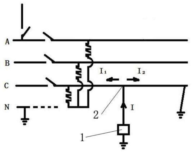
[0076] Such as figure 1 As shown, a ground fault occurs on the right side of the line in the figure, and it is only necessary to inject a detection signal I with a certain power at the detection point 2, (I=U÷Z, where U is the voltage applied to the detection point, and Z is the impedance of the wire )I is divided into two branches I 1 and I 2 , a faulty I 2 Through the earth to form a loop, there is no fault I 1 Almost zero, there is a difference in the current on both sides, that is, I 2 > I 1 , so it can be judged that the fault range is in the I of detection point 2 2 side; at detection point 2 I 2 By using the method of the present invention to select detection points for detection again, the fault range can be narrowed down again, and the fault point can be found after repeated several times; if the detection is performed in groups, the detection efficiency will be further improved.
[0077] In addition, when a ground fault occurs, the ground at the fault point i...
Embodiment 2
[0080] Such as figure 2 As shown, the bare conductor has a short-circuit fault between phases BC, the detection signal I is injected into the detection point 2 of phase C, and the ground terminal of the signal generator 1 is lapped to the conductor of phase B. Since there is a short-circuit point between the phases, a loop is formed, and I 2 >I 1 , it can be judged that the fault range is in I 2 side. This embodiment can also use Figure 10 -A structural form, the same effect can be achieved by lapping the B-phase conductor with a horizontal grounding rod (17).
[0081] According to the above method, the fault point can be found after repeated several times. Since the short-circuit circuit is not connected in series with an inductive load, this embodiment can use a DC detection signal or an AC detection signal.
[0082]For Embodiment 1 and Embodiment 2, the detection signal is any one or any combination of AC signals, DC signals, pulse signals, and different frequency si...
Embodiment 3
[0085] Such as Figure 4 As shown, a line fault detection device includes a detection module (3) and a signal module (16) with a signal generator (1), and the side of the signal module (16) is the detection module (3). The signal generator (1) and the signal module (16) can be arranged integrally or separately.
[0086] Such as Figure 8 As shown, preferably, the signal module (16) includes a first signal module (101) and a second signal module (102), and the first signal module (101) and the second signal module (102) are located in the detection module (3 ) on both sides. The first signal module and the second signal module successively input detection signals to the detection points on the faulty power line, and the detection modules successively detect the electrical characteristics on both sides of the detection points.
[0087] Preferably, the first signal module (101) and the second signal module (102) are electrically connected with a switching module (4), and the s...
PUM
 Abstract
Description
Claims
Application Information
 - R&D
- Intellectual Property
- Life Sciences
- Materials
- Tech Scout
- Unparalleled Data Quality
- Higher Quality Content
- 60% Fewer Hallucinations
Browse by: Latest US Patents, China's latest patents, Technical Efficacy Thesaurus, Application Domain, Technology Topic, Popular Technical Reports.
© 2025 PatSnap. All rights reserved.Legal|Privacy policy|Modern Slavery Act Transparency Statement|Sitemap|About US| Contact US: help@patsnap.com


