Adjustable reflecting-mirror Bipod flexible support structure, support device and assembling adjusting method

A flexible support and support device technology, applied in the field of space optics, can solve problems such as poor adjustment accuracy and low efficiency, and achieve the effects of improving structural rigidity and reliability, easy installation and adjustment, and ensuring adjustment accuracy.

Active Publication Date: 2017-11-07
XI'AN INST OF OPTICS & FINE MECHANICS - CHINESE ACAD OF SCI
View PDF3 Cites 13 Cited by
  • Summary
  • Abstract
  • Description
  • Claims
  • Application Information

AI Technical Summary

Problems solved by technology

[0005] The purpose of the present invention is to provide a flexible support structure, support device and adjustment method for an adjustable reflector Bipod, which solves the technical problems of poor adjustment accuracy and low efficiency in the traditional reflector support structure

Method used


Image

  • Adjustable reflecting-mirror Bipod flexible support structure, support device and assembling adjusting method
  • Adjustable reflecting-mirror Bipod flexible support structure, support device and assembling adjusting method
  • Adjustable reflecting-mirror Bipod flexible support structure, support device and assembling adjusting method

Examples


Embodiment 1

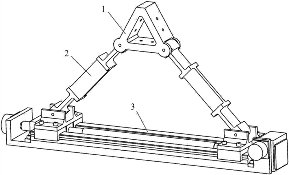
[0041] see figure 1 , the present embodiment is a flexible support structure for an adjustable mirror Bipod, including two flexible rods 2, the bottoms of the two flexible rods 2 are arranged on the bidirectional adjustment mechanism 3; the tops of the two flexible rods 2 pass through the triangular support frame 1 The two bottom corners of the triangular support frame 1 are respectively hinged with the tops of the two flexible rods 2 .

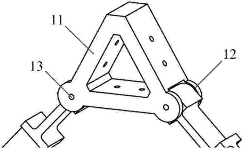
[0042] see figure 2 , the triangular support frame 1 in the present embodiment is the frame structure that the section that is made up of three panels 11 is equilateral triangle, and each panel 11 is all provided with two mounting holes for fixing the reflector, the triangular support frame 1 A flexible rod installation groove 12 is respectively arranged on the two bottom corners of the two bottom corners, and a rotating shaft 13 is arranged in the flexible rod installing groove 12, and the two flexible rods 2 can rotate around the rotating...

Embodiment 2

[0062] see Figure 9 , the present embodiment is a support device based on the flexible support structure of the adjustable mirror Bipod. This supporting device comprises three fixed inserts 5 that are centrally symmetrically arranged on the peripheral surface of the reflector 4, and an adjustable mirror Bipod flexible support structure 6 is installed at the bottom of each fixed insert 5; The mirror 4 is glued and fixed, and the fixed insert 5 is screwed and fixed to the top of the flexible rod in the Bipod flexible support structure 6 of the adjustable mirror; the centers of the three fixed inserts 5 coincide with the center of gravity of the reflector 4, and the three fixed inserts The plane where the center of 5 is perpendicular to the optical axis of reflector 4.

[0063] see Figure 10 , the fixed insert 5 includes an arc-shaped adhesive plate 51 and a triangular boss 52 located in the middle of the arc-shaped adhesive plate 51; It is located in the triangular support ...


PUM


Abstract

The invention belongs to the space optical technology field and especially relates to an adjustable reflecting-mirror Bipod flexible support structure, a support device and an assembling adjusting method. The adjustable reflecting-mirror Bipod flexible support structure comprises two flexible rods whose top portions are connected, and a bidirectional adjusting mechanism. The bidirectional adjusting mechanism comprises a fixing support and a bidirectional ball screw installed on the fixing support. Two ends of the bidirectional ball screw are provided with screw joints respectively. The bidirectional ball screw possesses two segments of screw threads whose screw pitches are the same and rotation directions are opposite. When the bidirectional ball screw is rotated, the two screw joints symmetrically move along the ball screw. Bottoms of the two flexible rods are hinged to the two screw joints respectively. The two flexible rods can rotate about a top portion connection point. The fixing support is provided with a servo motor used for driving the bidirectional ball screw to rotate and a potentiometer used for recording and feeding back a rotation direction and an angle of the bidirectional ball screw.

Description

technical field [0001] The invention belongs to the technical field of space optics, and in particular relates to a flexible support structure of an adjustable reflector Bipod, a support device and an assembly method thereof. Background technique [0002] The mirror is the core component of the space camera, and its surface shape accuracy and position accuracy directly affect the imaging quality of the optical system. In order to reduce the influence of adhesive stress and thermal stress caused by temperature changes on the surface shape accuracy of the reflector, the reflector is usually connected with the main load-bearing structure by using Bipod flexible support structure. During the installation and adjustment process of space camera equipment, the installation and adjustment of mirrors and supporting structures is an important link to ensure the optical performance of the whole machine. [0003] In February 2015, Zhang Limin and others from the Changchun Institute of ...

Claims


Application Information

Patent Timeline
Patent Type & Authority Applications(China)
IPC IPC(8): G02B7/18G02B7/183
CPCG02B7/181G02B7/183Y02E10/47
Inventor 刘贝王炜凤良杰屈艳军李旭鹏成鹏飞石进峰任国瑞王肖樊学武
Owner XI'AN INST OF OPTICS & FINE MECHANICS - CHINESE ACAD OF SCI
Why Eureka
Try Eureka