Cavity discharge method and system for cavity filter

A cavity filter and solution technology, applied in waveguide devices, data processing applications, prediction, etc., can solve problems such as poor cavity discharge effect

Active Publication Date: 2019-09-17
COMBA TELECOM TECH (GUANGZHOU) CO LTD
View PDF2 Cites 0 Cited by
  • Summary
  • Abstract
  • Description
  • Claims
  • Application Information

AI Technical Summary

Problems solved by technology

[0005] Based on this, it is necessary to provide a method and system for cavity filter cavity discharge for the problem of poor cavity discharge effect

Method used


Image

  • Cavity discharge method and system for cavity filter
  • Cavity discharge method and system for cavity filter
  • Cavity discharge method and system for cavity filter

Examples


Embodiment Construction

[0031] The technical solution of the present invention will be described below in conjunction with the accompanying drawings.

[0032] Such as figure 1 As shown, the embodiment of the present invention provides a cavity filter cavity removal method, which may include the following steps:

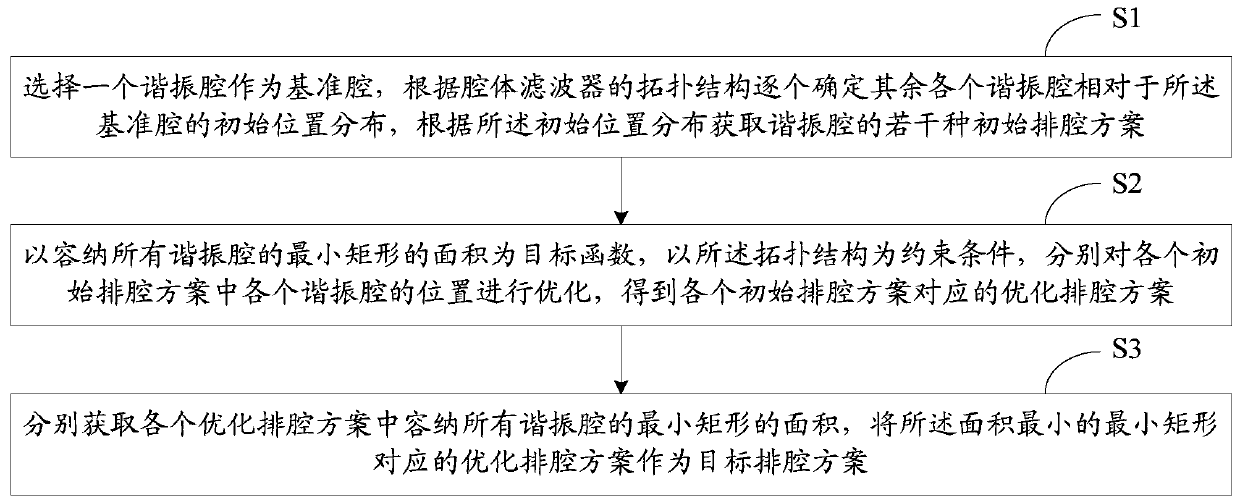
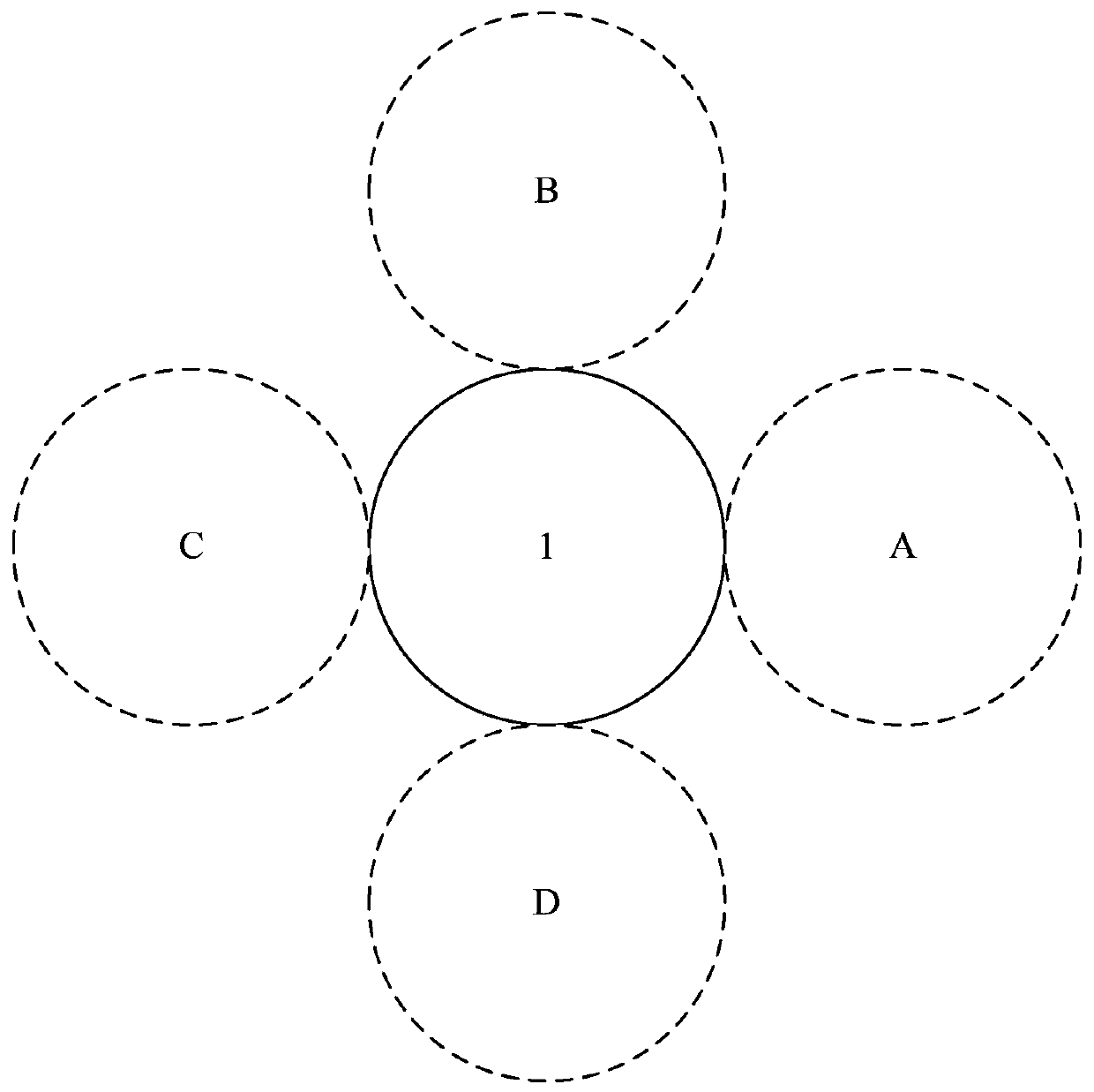
[0033] S1, select a resonant cavity as the reference cavity, determine the initial position distribution of the remaining resonant cavities relative to the reference cavity one by one according to the topology of the cavity filter, and obtain several initial cavity discharges of the resonant cavity according to the initial position distribution Program;

[0034] The selectivity of the cavity filter is very good, and the coaxial cavity filter is a typical cavity filter. The cavity filter is mainly composed of a resonant cavity, an absorbing cavity, a coupling ring, an adjusting rod and a locking device. Because the cavity filter mainly converts the electric field and the magnetic field, ra...


PUM


Abstract

The invention relates to a cavity arrangement method and a cavity arrangement system of a cavity filter. The cavity management method comprises steps that a resonant cavity is selected to be used as a reference cavity, and according to the topological structure of the cavity filter, the initial position distribution of every other resonant cavity with respect to the reference cavity is determined, and according to the initial position distribution, a plurality of cavity arrangement schemes of the resonant cavities are acquired; by taking an area of a minimum rectangle capable of accommodating all of the resonant cavities as a target function, and by taking the topological structure as a constraint condition, the positions of the various resonant cavities in the various initial cavity arrangement schemes are optimized respectively, and the corresponding optimized cavity arrangement schemes of the various initial cavity arrangement cavities are acquired; the areas of the minimum rectangles capable of accommodating all of the resonant cavities in the various optimized cavity arrangement schemes are acquired respectively, and the optimized cavity arrangement scheme corresponding to the minimum rectangle having the minimum area is used as a target cavity arrangement scheme.

Description

technical field [0001] The present invention relates to the technical field of cavity filters, in particular to a method and system for cavity discharge of cavity filters. Background technique [0002] In the field of modern mobile communication, cavity filter is a commonly used radio frequency device, which is used for frequency selection filtering of mobile communication. In the process of cavity filter design, after determining the number, size, and topological relationship of the cavity, the designer needs to arrange the position of the cavity, which is called cavity arrangement. The basic requirement of cavity row is: under the premise of satisfying the spacing relationship between coupled cavities and non-intersecting cavities, minimize the filter volume and reduce material waste, thereby reducing device manufacturing costs and realizing filter miniaturization. [0003] Due to the certainty of the depth of the cavity, the method of arranging circles (or polygons) in t...

Claims


Application Information

Patent Timeline
Patent Type & Authority Patents(China)
IPC IPC(8): H01P11/00G06Q10/04
Inventor 边江邸英杰孟弼慧林显添
Owner COMBA TELECOM TECH (GUANGZHOU) CO LTD
Why Eureka
Try Eureka