Laser-scanning-type power-transmission-line foreign matter remote removing apparatus and application method thereof

A laser scanning and clearing device technology, which is applied in the field of power transmission and transformation, can solve the problems affecting the working stability of lasers and inconvenient operation, and achieve the effects of ensuring work efficiency and stability, being easy to carry and transport, and improving reliability

Active Publication Date: 2017-11-07
XI'AN INST OF OPTICS & FINE MECHANICS - CHINESE ACAD OF SCI
View PDF12 Cites 13 Cited by
  • Summary
  • Abstract
  • Description
  • Claims
  • Application Information

AI Technical Summary

Problems solved by technology

[0004] At present, the laser remote removal device removes foreign matter on the transmission line at a high angle and at a long distance. The laser is placed in the launch tube and adjusts the angle following the launch tube. When multi-point and long-term removal of foreign matter on the transmission line, the laser will be used multiple times. Handling and swinging will affect the working stability of the laser
The aiming device is installed above the launch tube. When working at a high angle, it will tilt up with the launch tube. The operator needs to bend over to aim at the target, which is inconvenient to operate

Method used


Image

  • Laser-scanning-type power-transmission-line foreign matter remote removing apparatus and application method thereof
  • Laser-scanning-type power-transmission-line foreign matter remote removing apparatus and application method thereof
  • Laser-scanning-type power-transmission-line foreign matter remote removing apparatus and application method thereof

Examples


Embodiment Construction

[0045] The structure of the present invention will be described in detail below in conjunction with three implementations:

[0046] The first embodiment:

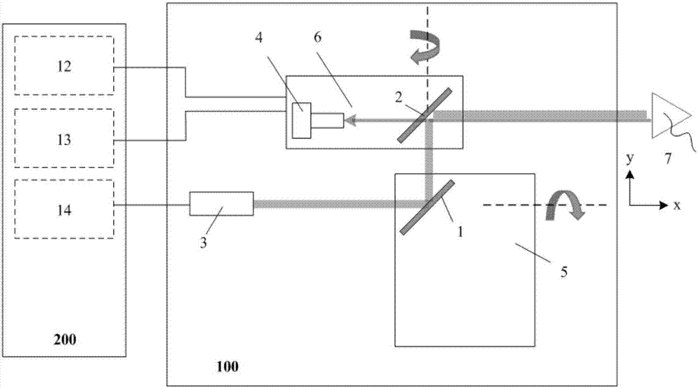
[0047] This embodiment is the basic structure of the present invention, see figure 1 As shown, the device includes: a control system 200 and a transmitting device 100;

[0048] Wherein: the emission device 100 includes a first scanning mirror 1, a second scanning mirror 2, a laser 3, an imaging lens 4, a first turntable 5 and a second turntable 6; wherein, the first scanning mirror 1 is installed on the first turntable 5 on; the second scanning mirror 2 and the imaging lens 4 are installed on the second turntable 6;

[0049] The outgoing laser beam of the laser 3 passes through the first scanning mirror 1 and the second scanning mirror 2 to reflect on the foreign object 7 to be removed in sequence, and the imaging lens 4 is always facing the foreign object 7 to be removed and imaging it;

[0050] The first scanning mirro...


PUM


Abstract

The invention relates to a laser-scanning-type power-transmission-line foreign matter remote removing apparatus and an application method thereof. The apparatus comprises a control system and an emitting device. The emitting device comprises a first scanning mirror, a second scanning mirror, a laser, an imaging lens, a first rotation table and a second rotation table. The first scanning mirror is installed on the first rotation table. The second scanning mirror and the imaging lens are installed on the second rotation table. An emergent laser beam of the laser successively passes through the first scanning mirror and the second scanning mirror and is reflected to a foreign matter to be removed. The imaging lens directly faces the foreign matter to be removed and carries out imaging on the foreign matter to be removed. A control system is used for controlling work of each component in the emitting device. He application method comprises the following steps of 1, initialization; 2, range finding guiding; and 3, foreign matter removing. In the invention, overadjustment does not need to be performed on the apparatus and the foreign matter on any direction of the power transmission line can be removed so that work efficiency is greatly increased.

Description

technical field [0001] The invention belongs to the technical field of power transmission and transformation, and relates to a laser scanning type transmission line foreign matter remote removal device and an application method thereof. Background technique [0002] Transmission lines are distributed in many areas, with complex terrain and harsh environment. During the operation and maintenance process, kites, advertising cloth, plastic cloth and other foreign objects are often entangled, which will cause short circuits, power outages and other accidents. May cause human and livestock casualties. The traditional method of removing foreign objects on overhead routes is mainly based on insulating rods, foreign object removal rods, climbing vehicles, bucket trucks, hanging baskets and other tools, which generally have the disadvantages of long time-consuming, difficult operation, high risk, and power outage operations. [0003] Laser removal of foreign matter is a new method. ...

Claims


Application Information

Patent Timeline
Patent Type & Authority Applications(China)
IPC IPC(8): H02G1/02G01S17/08G01S17/89
CPCH02G1/02G01S17/08G01S17/89
Inventor 吴冰静齐文博薛艳博李奇许瑞华何俊华
Owner XI'AN INST OF OPTICS & FINE MECHANICS - CHINESE ACAD OF SCI
Why Eureka
Try Eureka