Permanent magnet compound direct drive motor

A direct drive motor, permanent magnet technology, applied in synchronous machines, electrical components, electromechanical devices, etc., can solve the problems of high cost, difficult industrialization, difficult design, manufacture, and assembly of magnetic control rings, and achieve the effect of simple structure

Inactive Publication Date: 2017-11-07
南京金冠永磁科技有限公司
View PDF0 Cites 5 Cited by
  • Summary
  • Abstract
  • Description
  • Claims
  • Application Information

AI Technical Summary

Problems solved by technology

In recent years, scientific and technological workers at home and abroad have proposed a 3-gap permanent magnet composite motor scheme. Composite motor scheme, the single air gap permanent magnet composite motor scheme is relatively simple, but the design, manufacture and assembly of the magnetic adjustment ring are difficult, and it is difficult to realize industrialization

Method used


Image

  • Permanent magnet compound direct drive motor
  • Permanent magnet compound direct drive motor

Examples


Embodiment 1

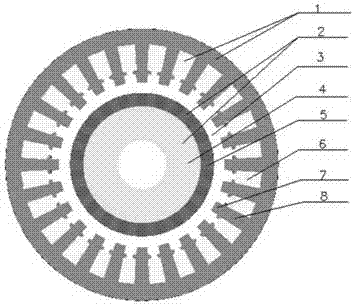
[0021] A permanent magnet composite direct drive inner rotor motor provided in this embodiment is more specifically a permanent magnet composite direct drive inner rotor motor, which is characterized in that it includes an iron core stator 1 and a permanent magnet rotor 2, and the iron core stator There is an air gap 3 between 1 and the permanent magnet rotor 2; the iron core stator 1 is composed of a winding 6 and a magnetically permeable material sheet 8 with slots; the teeth of the magnetically permeable material 8 protrude radially outward in a block shape or The shape forms a magnetic modulation block 7, and a plurality of magnetic modulation blocks 7 along the circumferential direction form a magnetic modulation ring; the permanent magnet rotor 2 is composed of several permanent magnets 5 and a yoke 4.

[0022] When the stator coil of the motor is energized, the coil induced magnetic field is modulated by the special modulation ring, and the modulated magnetic field is th...

Embodiment 2

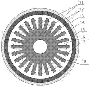
[0026] This embodiment provides a permanent magnet composite direct drive external rotor motor, more specifically a permanent magnet composite direct drive external rotor motor, which is characterized in that it includes an iron core stator 11 and a permanent magnet rotor 12, and the iron core stator 11 Inside the permanent magnet rotor 12, there is an air gap 13 between the iron core stator 11 and the permanent magnet rotor 12; the iron core stator 11 is composed of a winding 16 and a magnetic material sheet 18 with tooth slots; the tooth edges of the magnetic material 18 A magnetic modulation block 17 protrudes radially outward in the shape of a block or other shapes, and a plurality of magnetic modulation blocks 17 along the circumferential direction form a magnetic modulation ring; the permanent magnet rotor 12 is composed of several permanent magnets 15 and a yoke 14 .

[0027] When the iron core stator coil is energized, the inductive magnetic field is adjusted through th...


PUM


Abstract

The invention discloses a permanent magnet compound direct drive motor, which is characterized in that it comprises an iron core stator 1 and a permanent magnet rotor 2, and an air gap 3 is provided between the iron core stator 1 and the permanent magnet rotor 2; the iron core stator 1 is composed of a winding 6 and a magnetically permeable material sheet 8 with tooth grooves; the teeth of the magnetically permeable material 8 protrude outward in the radial direction in a block shape or other shapes to form a magnetic modulation block 7, and a plurality of magnetic modulation blocks 7 along the circumferential direction form a magnetic modulation block 7 Magnetic ring; the permanent magnet rotor 2 is composed of several permanent magnets 5 and a yoke 4 . When the iron core stator coil is energized, the inductive magnetic field is adjusted through the magnetic adjustment ring formed by the magnetic adjustment block 7, and the magnetic field after magnetic adjustment forms a mutual meshing effect with the permanent magnet rotor magnetic field, thereby realizing high torque and low speed of the permanent magnet rotor Rotate function. By integrating each magnetic block 7 of the magnetic ring with the teeth of the magnetic material sheet 8, the structure is simple, and the function of high torque and low speed can be realized at low cost. Different speed outputs can be designed according to needs, which can replace the gearbox , Maintenance-free, high efficiency, high reliability.

Description

technical field [0001] The invention relates to a motor, in particular to a permanent magnet composite direct drive motor. Background technique [0002] Gear transmission is the basis of industrial transmission. Gear transmission can be seen everywhere, but the requirements of gear transmission are high, and it is easy to leak oil, wear gears, even broken shafts and teeth, and spontaneous combustion. The lubricating oil, the lubricating oil has insulation problems and so on. Therefore, scientific and technological workers have been pursuing the realization of motor direct drive. In recent years, motor direct drive technology has developed rapidly, but it has also encountered bottlenecks. The current motor direct drive technology is mainly realized by increasing the number of pole pairs of motors, such as torque motors and wind turbines. etc. Increasing the number of pole pairs of the motor makes the volume along the radial direction larger, the weight is heavy, the cost is...

Claims


Application Information

Patent Timeline
Patent Type & Authority Applications(China)
IPC IPC(8): H02K21/02
CPCH02K21/028
Inventor 王向东林起崟周丽萍牛建涛皋世俊
Owner 南京金冠永磁科技有限公司
Why Eureka
Try Eureka