Magnetic coupling transmission device

A transmission device, magnetic coupling technology, applied in the direction of permanent magnet clutch/brake, electromechanical device, electric vehicle, etc., can solve the problems of complex structure and difficult assembly process, achieve small size, low assembly process difficulty, reduce production cost effect

Active Publication Date: 2017-11-07
HUNAN UNIV
View PDF4 Cites 1 Cited by
  • Summary
  • Abstract
  • Description
  • Claims
  • Application Information

AI Technical Summary

Problems solved by technology

[0004] In view of the above situation, the purpose of the present invention is to provide a magnetic coupling transmission device, which adopts a structure in which the stator is arranged on the outermost side and the two ends are respectively connected to the inner and outer rotor shafts, so as to overcome the defects of complex structure and difficult assembly process in the prior art; and The overall structure is scientific and reasonable, easy to install and use, the equipment is small in size and light in weight, has a broad market prospect, and is easy to promote and use

Method used


Image

  • Magnetic coupling transmission device
  • Magnetic coupling transmission device
  • Magnetic coupling transmission device

Examples


Embodiment 1

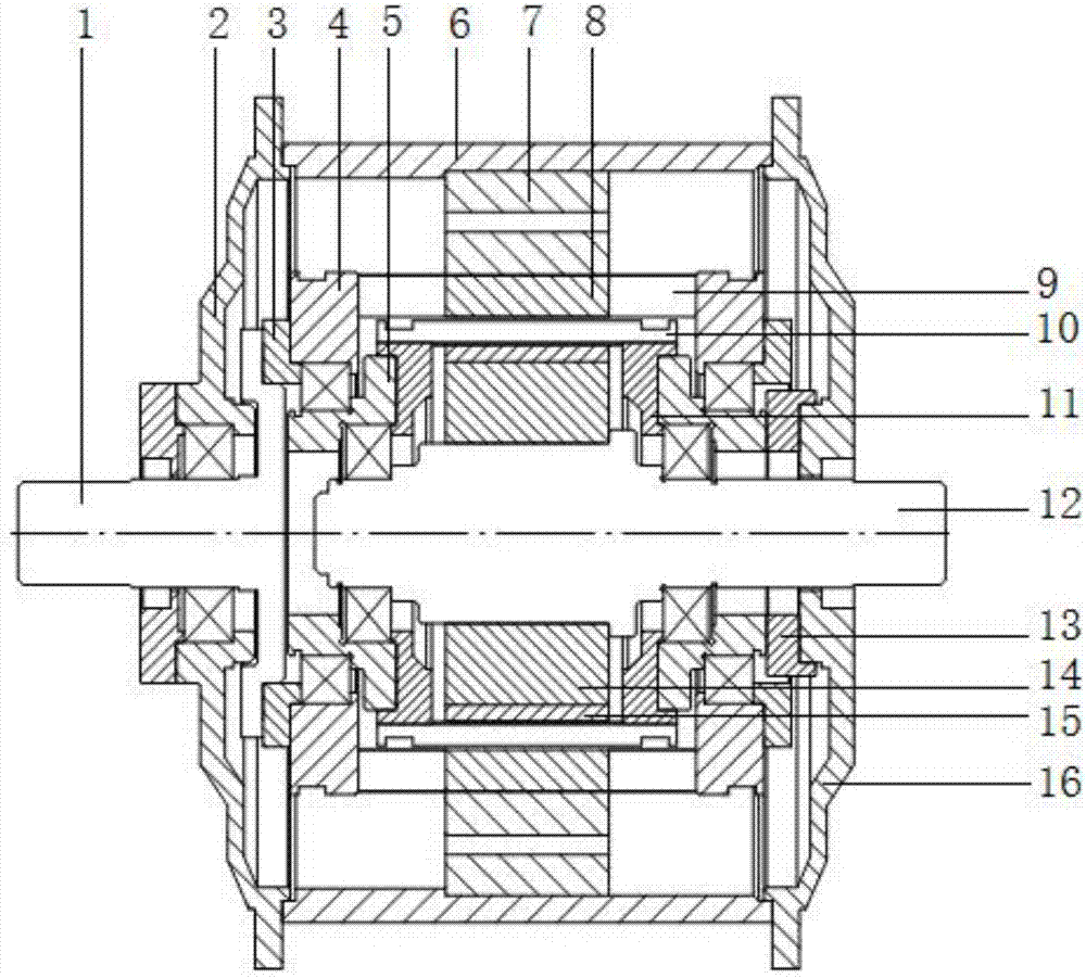
[0041] Embodiment 1 of the present invention: when three-phase alternating current is passed into the armature winding, the outer rotor shaft and the inner rotor shaft can be simultaneously driven to rotate through magnetic coupling, and the outer rotor shaft and / or the inner rotor shaft are used as output terminals to connect to an external load. Now the present invention is used as a permanent magnet motor; wherein the outer rotor shaft rotational speed is lower, while the inner rotor shaft rotational speed is higher, and the rotational direction of the outer rotor shaft and the inner rotor shaft is opposite; the calculation formula of both rotating speeds is as follows: Let f is the current frequency, P in is the number of pole pairs of the inner rotor permanent magnet, P out is the number of pole pairs of the permanent magnet of the outer rotor, then the shaft speed of the inner rotor n in =60f / P in , the rotational speed of the outer rotor shaft n out =P in ×n in / P ...

Embodiment 2

[0042] Embodiment 2 of the present invention: When the armature winding is not energized or the armature winding is not installed, the outer rotor shaft or the inner rotor shaft is connected to the external power as the input end, and the corresponding other end is connected to the external load as the output end. At this time, the magnetic coupling transmission device can be used as a speed changer; if the outer rotor shaft is used as the input end to connect with the external power, and the inner rotor shaft is used as the output end to connect with the external load, then the present invention can be used as a speed increaser; if the inner rotor shaft The shaft is connected with external power as an input end, and the outer rotor shaft is connected with an external load as an output end. At this time, the present invention is used as a reducer to increase output torque.

Embodiment 3

[0043] Embodiment 3 of the present invention: when the outer rotor shaft or inner rotor shaft is used as the input end to connect with external power and drive to rotate, a three-phase alternating current can be generated in the armature winding of the outer stator, and at the same time, the armature winding is used as the output end to connect to the external When the load is on, the present invention can be used as a generator at this time, and is especially suitable for low-speed, high-torque applications such as wind power generation.


PUM


Abstract

A magnetic coupling transmission device comprises an outer stator disposed on an outermost side, and a group including an outer rotor, a modulating device and an inner rotor and coaxial with the outer stator. Any two adjacent ones of the outer stator, the outer rotor, the modulating device and the inner rotor have a gap therebetween. The outer rotor and the inner rotor both include permanent magnets. The outer stator includes a stator core and an armature winding and is disposed in a housing. Both sides of the housing are fixedly connected to the left end cover and the right end cover respectively. The axial centers of the left end cover and the right end cover are connected to one end of an outer rotor shaft and one end of an inner rotor shaft respectively. The stator is arranged on the outermost side and the two ends of the stator are connected with the inner and outer rotor shafts respectively so as to overcome complex structure and difficult assembly process in the prior art. The magnetic coupling transmission device is scientific and rational in overall layout, easy to install and use, small in size, light in weight, low in maintenance cost, widely used in transmission technical field such as wind power generation, electric vehicles and the like.

Description

technical field [0001] The invention relates to the technical field of electromechanical equipment, in particular to a magnetic coupling transmission device. Background technique [0002] Traditional low-speed high-torque output is achieved by setting a reducer. In production practice, it is found that this indirect transmission can reduce the reliability and efficiency of mechanical transmission; as the manufacturing industry increases the reliability and system efficiency of mechanical transmission The requirements continue to increase, and the resulting direct drives such as magnetic coupling transmissions have been developed rapidly; compared with traditional mechanical transmissions, magnetic coupling transmissions have three advantages: ① non-contact transmission, no friction, low noise and weak vibration; ② no lubrication, low maintenance cost; ③ flexible non-contact connection, with automatic overload protection capability. [0003] However, in order to improve the ...

Claims


Application Information

Patent Timeline
Patent Type & Authority Applications(China)
IPC IPC(8): H02K49/10
CPCH02K49/106Y02T10/64
Inventor 刘晓张晓旭陈哲黄守道
Owner HUNAN UNIV
Why Eureka
Try Eureka