Robot polishing equipment

A robot and equipment technology, applied in the direction of grinding/polishing equipment, metal processing equipment, surface polishing machine tools, etc., can solve the problems of low degree of mechanization, polishing at different angles, and small application range, so as to reduce labor intensity and improve stability Sexuality, enhance the effect of polishing quality

Inactive Publication Date: 2017-11-10
ANHUI HAITUO ZHIYONG INTELLIGENT EQUIP CO LTD
View PDF0 Cites 6 Cited by
  • Summary
  • Abstract
  • Description
  • Claims
  • Application Information

AI Technical Summary

Problems solved by technology

[0003] The purpose of the present invention is to overcome the problems of inconvenient adjustment existing in the existing workpiece polishing process, inability to polish workpieces at different positions and angles, low degree of mechanization, and small scope of application, and to prov

Method used


Image

  • Robot polishing equipment
  • Robot polishing equipment
  • Robot polishing equipment

Examples


Embodiment 1

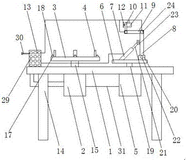
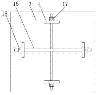
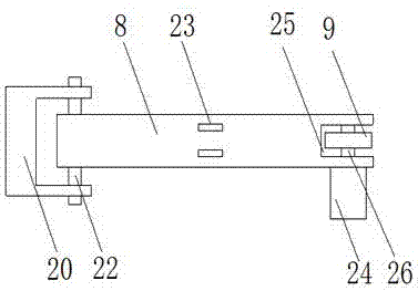
[0022] As attached Figure 1-5 As shown, a robot polishing equipment includes a console 1, a motor 1, a bearing plate 3, a limit block 4, a motor 5, a backing plate 6, a hydraulic cylinder 7, a connecting plate 8, a connecting plate 9, and a connection The board three 10, the motor three 11, the polishing disc 12 and the controller 13 are characterized in that: the operating table 1 is set on the support 14, and the motor one and the second motor 5 are respectively set on the operating table 1. And the motor one 2 and the motor two 5 are respectively provided with a transmission shaft 15 and a transmission shaft 19, the bearing plate 3 is arranged on the transmission shaft 15, and a positioning slot 16 is provided on the bearing plate 3. The limit block 4 is provided with a mounting plate 17, and the mounting plate 17 is set on the bearing plate 3 through a mounting bolt 18, and the backing plate 6 is provided on the second transmission shaft 27 and is provided on the backing p...

Embodiment 2

[0030] As attached Image 6 As shown, a robot polishing equipment includes a console 1, a motor 1, a bearing plate 3, a limit block 4, a motor 2 5, a backing plate 6, a hydraulic cylinder 7, a connecting plate 8, a connecting plate 9, and a connection The board three 10, the motor three 11, the polishing disc 12 and the controller 13, are characterized in that the operating table 1 is set on the support 14, the motor one and the two motors 5 are respectively set on the operating table 1. And the motor one 2 and the motor two 5 are respectively provided with a transmission shaft 15 and a transmission shaft 19, the bearing plate 3 is provided on the transmission shaft 15 and a positioning slot 16 is provided on the bearing plate 3. The limit block 4 is provided with a mounting plate 17, and the mounting plate 17 is set on the bearing plate 3 through a mounting bolt 18, and the backing plate 6 is provided on the second transmission shaft 27 and is provided on the backing plate 6. ...


PUM


Abstract

The invention discloses a robot polishing device, which comprises an operating table, a motor one, a bearing plate, a limit block, a motor two, a backing plate, a hydraulic cylinder, a connecting plate one, a connecting plate two, a connecting plate three, a motor three, and a polishing disc and the controller, characterized in that: the operating table is set on the bracket, the motors 1 and 2 are respectively set on the operating table, the bearing plate is set on the transmission shaft 1, and the position limiting The block is provided with a mounting plate, the backing plate is set on the transmission shaft 2, the hydraulic cylinder is set on the backing plate, and the connecting plate 3 is connected to the rotating shaft in the upper limit groove of the connecting plate 2 , the motor three is arranged on the connection board three, and the controller is arranged on the operating table. In the present invention, a bearing plate is arranged on the transmission shaft 1 of the motor 1, and a position-adjustable limit block is arranged on the load plate, so that the stability of the workpiece in the polishing process is improved through the limit block, and the polishing quality of the workpiece is enhanced. .

Description

Technical field [0001] The invention relates to the technical field of polishing processing, in particular to a robot polishing equipment for workpiece processing. Background technique [0002] At present, in the process of workpiece processing, in order to improve the finish and quality performance of the workpiece, the workpiece will be polished after the workpiece is processed. The traditional method is mostly manual operation, which not only has high labor intensity and low work efficiency, but also has Due to the low uniformity of polishing quality, the yield of the workpiece is reduced. The existing methods mostly use mechanical polishing. Although mechanical polishing solves the problems of manual labor intensity and low work efficiency, it is inconvenient to adjust and cannot be performed on the workpiece. Different positions, different angles of polishing, low degree of mechanization, and small scope of application are insufficient. Summary of the invention [0003] The ...

Claims


Application Information

Patent Timeline
IPC IPC(8): B24B29/00B24B41/06B24B47/08B24B55/00B24B41/02B24B51/00
CPCB24B29/00B24B41/02B24B41/06B24B47/08B24B51/00B24B55/00
Inventor 冯继友梁振华
Owner ANHUI HAITUO ZHIYONG INTELLIGENT EQUIP CO LTD
Why Eureka
Try Eureka