
3D mobile phone back cover and molding process thereof

A mobile phone back cover, 3D technology, applied in the direction of telephone structure, telephone communication, electrical components, etc., can solve the problems that the battery cannot be charged wirelessly, the back cover of the mobile phone is hot, dry, etc.

Pending Publication Date: 2017-11-14
FUJIAN SHISHI TONGDA ELECTRICAL APPLIANCE
View PDF5 Cites 25 Cited by
  • Summary
  • Abstract
  • Description
  • Claims
  • Application Information

AI Technical Summary

Problems solved by technology

[0002] Traditionally sold mobile phone back covers are generally made of plastic, and various effects can be achieved by spraying various paints on the plastic shell, but the wear resistance of plastic is poor and the strength is not enough, so that the outer surface of the plastic mobile phone back cover The side of the back cover facing the main board of the mobile phone is the inner surface, and the side facing away from the main board of the mobile phone is the outer surface) is easily damaged or scratched. In order to improve the wear resistance and strength of the back cover of the mobile phone, it is also made of stainless steel, but This kind of stainless steel mobile phone back cover is too bulky to hold in the hand. Therefore, a metal mobile phone back cover made of metal material appears on the market. Because aluminum has the advantages of light weight, high wear resistance, good hand feeling and high strength , the existing metal mobile phone back cover is generally an aluminum mobile phone back cover
However, the metal characteristics of the aluminum mobile phone back cover will interfere with the signal, so that the battery cannot be charged wirelessly, and cannot be applied to the 5G network, and the back cover of the mobile phone will heat up after long-term use

Method used


Image

  • 3D mobile phone back cover and molding process thereof

Examples


Embodiment Construction

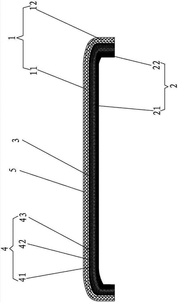
[0024] A 3D mobile phone back cover of the present invention, such as figure 1 As shown, it includes a body with a back plate that fits the back of the mobile phone and a side frame that fits the side wall of the mobile phone,

[0025] The body includes a glass back cover 1 and a PET film 2. The glass back cover 1 has a flat plate part 11 that matches the size of the back plate and a side bend part 12 that matches the size of the side frame. The side bend part 12 uses a glass bending machine and a flat plate. The part 11 is integrally formed by hot bending. The glass back cover adopts the 2320 series of Corning glass. The PET film 2 has an inner flat part 21 that matches the size of the back plate and an inner bend 22 that matches the size of the side frame. The bent part 22 and the inner flat part 21 are integrally punched and formed by a punching process. The glass back cover 1 is formed by a flat part 11 and a side bent part 12 to form a cavity. The PET film 2 is in the cavity...


PUM

PropertyMeasurementUnit
Thicknessaaaaaaaaaa
Thicknessaaaaaaaaaa
Thicknessaaaaaaaaaa

Abstract

The invention discloses a 3D mobile phone back cover which comprises a body. The body comprises a glass back cover and a PET film. The glass back cover is integrally formed by a glass bending machine through hot bending. The PET film is punched and cut. The PET film is arranged in the glass back cover. The inner flat plate part coincides with a flat plate part. A side bending part coincides with an inner side bending part. The PET film is vacuum laminated with the glass back cover through a transparent optical adhesive layer. An ink pattern layer is arranged on one side, which fits the glass back cover, of the PET film. According to the 3D mobile phone back cover provided by the invention, the glass back cover and the PET film are free of signal interference, so that the signal of a mobile phone is strong; wireless charging is realized; the 3D mobile phone back cover is suitable for the application of a 5G network; the glass has the advantages of light weight, being thin, scratch resistance and heat dissipation, so that the mobile phone back cover has the corresponding effects of light weight, being thin, scratch resistance and heat dissipation; and the mobile phone is prevented from heating. The invention further discloses a molding process of the 3D mobile phone back cover.

Description

Technical field [0001] The invention relates to mobile phone accessories, in particular to a mobile phone back cover and its forming process. Background technique [0002] Traditionally sold mobile phone back covers are generally made of plastic, and various effects are achieved by spraying various paints on the plastic shell. However, the plastic has poor wear resistance and insufficient strength, which makes the outer surface of the plastic phone back cover (mobile phone The side of the back cover facing the motherboard of the mobile phone is the inner surface, and the side facing the motherboard of the mobile phone is the outer surface.) It is easy to be damaged or scratched. In order to improve the wear resistance and strength of the mobile phone back cover, it is also made of stainless steel. This kind of stainless steel mobile phone back cover is too cumbersome to hold in the hand. As a result, a metal mobile phone back cover made of metal has appeared on the market. Becaus...

Claims


Application Information

Patent Timeline
IPC IPC(8): H04M1/02
CPCH04M1/026
Inventor 周亮生
Owner FUJIAN SHISHI TONGDA ELECTRICAL APPLIANCE
Learn More