
A laser spiral milling and grinding hole-making composite device and hole-making method

A compound device and helical milling technology, which is applied in the direction of manufacturing tools and other manufacturing equipment/tools, can solve the problems of hole wall burns, holes prone to taper holes, fiber faults, etc., to improve efficiency, reduce costs, and improve hole making The effect of precision

Inactive Publication Date: 2019-04-12
XI AN JIAOTONG UNIV
View PDF5 Cites 0 Cited by
  • Summary
  • Abstract
  • Description
  • Claims
  • Application Information

AI Technical Summary

Problems solved by technology

At present, laser drilling and spiral milling drilling are new hole-making processes proposed for difficult-to-machine materials. Laser cutting with adjustable radius can realize processing of different apertures, but the processed holes are prone to defects such as taper holes and hole wall burns. , but the burrs at the inlet and outlet positions of the composite hole are well controlled, and the precision of the spiral milling hole is high, but the burrs are easy to form at the outlet and the inlet, and fiber faults are prone to occur in the middle

Method used


Image

  • A laser spiral milling and grinding hole-making composite device and hole-making method
  • A laser spiral milling and grinding hole-making composite device and hole-making method
  • A laser spiral milling and grinding hole-making composite device and hole-making method

Examples


Embodiment Construction

[0024] The present invention will be described in further detail below in conjunction with the accompanying drawings.

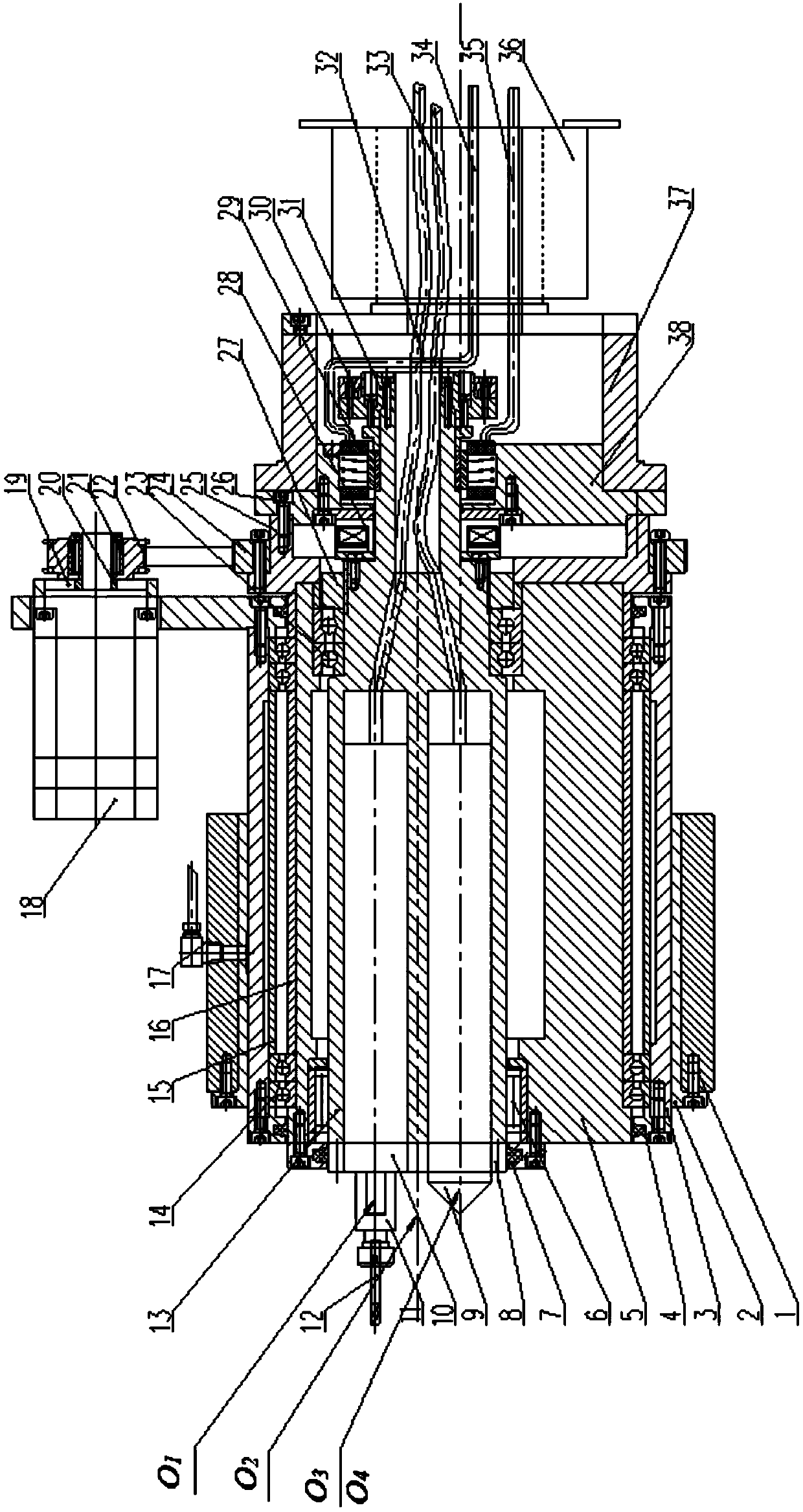
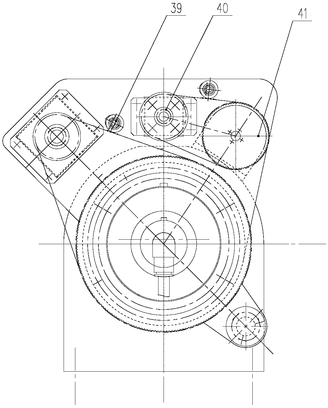
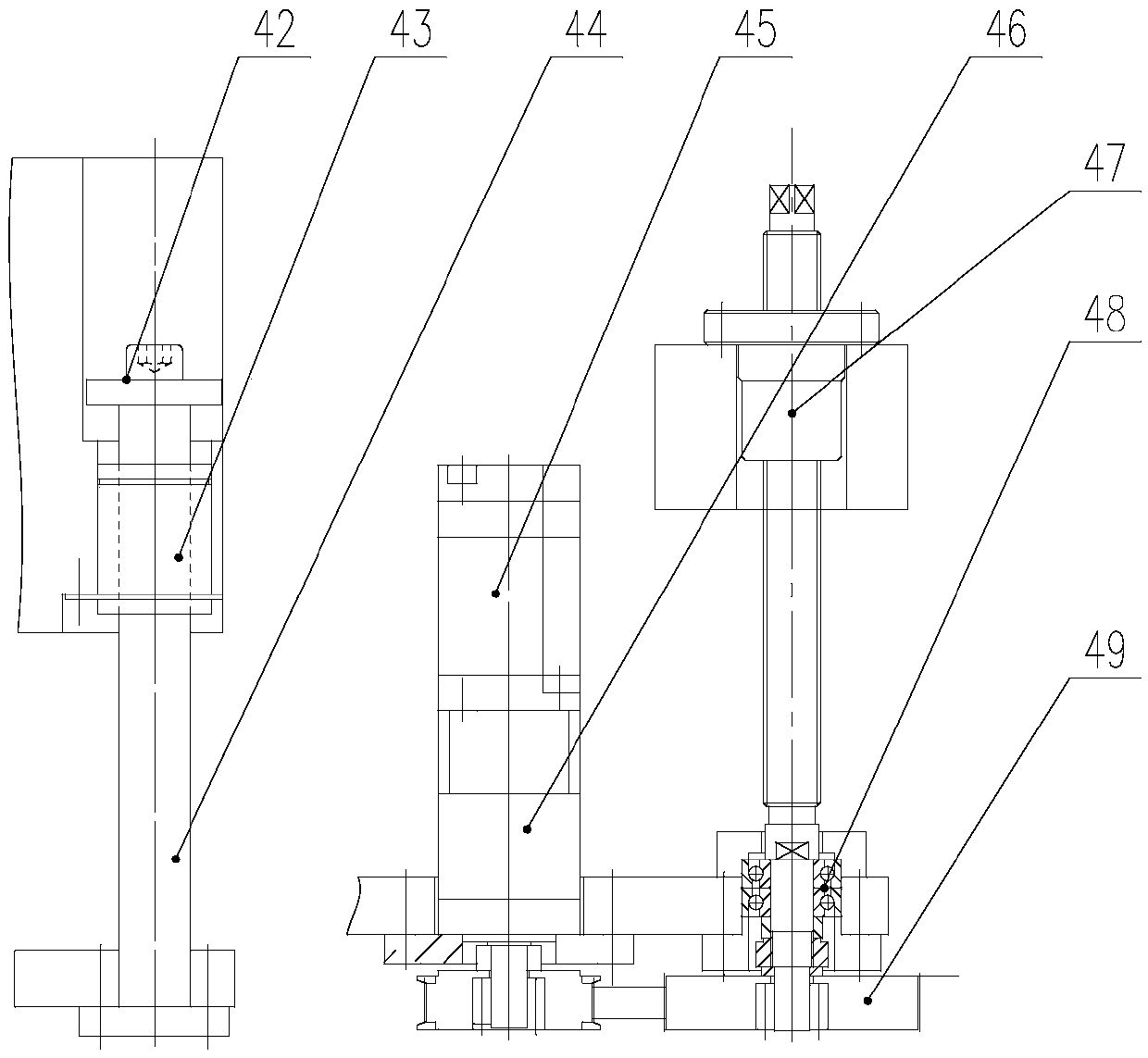
[0025] see Figure 1-4 According to the present invention, the laser spiral milling and hole-making compound device includes a laser generator 9 and a high-speed electric spindle 10 respectively installed in the two eccentric holes of the adjustment shaft 13 . The adjustment shaft 13 is supported and installed in the eccentric hole of the revolving main shaft 5 through the needle roller bearings 6 and angular contact bearings 23 arranged at both ends thereof. The sleeve 3 drives the entire spindle system to complete the axial feed in the feed sliding sleeve 2, and the feed sliding sleeve 2 is installed in the feed base 1. The end of the adjustment shaft 13 and the revolving main shaft 5 is provided with an electromagnetic brake 28 capable of locking the relative positions of the two and a torque motor 29 for adjusting the axial distance between the high-spee...


PUM


Abstract

The invention relates to a laser spiral machining, grinding and drilling compound device and a drilling method. The drilling compound device comprises a laser generator and a high-speed electric spindle arranged in two eccentric holes of an adjusting shaft; the adjusting shaft is supported and installed in an eccentric hole of a revolution spindle through a needle bearing and an angular contact bearing arranged at two ends of the adjusting shaft; the revolution spindle is arranged in a spindle sleeve and is connected with a revolution motor through a belt pulley; the spindle sleeve drives a whole spindle system to accomplish axial feeding in a feeding sliding sleeve; the feeding sliding sleeve is arranged in a feeding base; and an electromagnetic band-type brake and a torque motor are arranged at the end parts of the adjusting shaft and the revolution spindle. The electromagnetic band-type brake firstly locks the adjusting shaft and the revolution spindle, the revolution motor drives the revolution spindle to revolute through the belt pulley, the high-speed electric spindle drives a grinding head to rotate at a high speed so as to grind a hole wall, and a feeding motor drives the spindle sleeve to axially feed through a screw rod so as to accomplish spiral machining, grinding and correcting of a processed hole. According to the laser spiral machining, grinding and drilling compound device and the drilling method provided by the invention, the drilling accuracy is high, the drilling efficiency can be improved, and the processing cost is reduced.

Description

technical field [0001] The invention belongs to the field of composite material processing, and in particular relates to a laser spiral milling and grinding hole-making composite device and a hole-making method. Background technique [0002] In order to meet the actual needs of my country's aviation and aerospace industries, a large number of new composite materials account for an increasing proportion of aviation and spacecraft. Typical examples include carbon fiber composite materials, glass fiber reinforced composite materials, and quartz ceramic matrix reinforced composite materials. composite material. The advantages of the above materials are high hardness, corrosion resistance, high temperature resistance, high strength, and low quality, but at the same time, the problem is that the equipment using the above materials has poor processability. Especially in the hole making process of difficult-to-machine materials, problems such as delamination, burrs, decomposition, a...

Claims


Application Information

Patent Timeline
Patent Type & Authority Patents(China)
IPC IPC(8): B23P23/00
CPCB23P23/00
Inventor 王磊卢秉恒
Owner XI AN JIAOTONG UNIV
Learn More