Multi-degree of freedom injection device for sintering and use method of same

A technology of blowing device and degree of freedom, which is applied in the field of blowing device and multi-degree-of-freedom blowing device, which can solve the problems that the distance is difficult to ensure a reasonable range, the degree of freedom is not high, and the distance is difficult to guarantee, so as to improve the degree of freedom and Adjustability, degree of freedom and adjustability are improved, and the effect of high degree of intelligence

Active Publication Date: 2017-11-17
ZHONGYE-CHANGTIAN INT ENG CO LTD
View PDF8 Cites 5 Cited by
  • Summary
  • Abstract
  • Description
  • Claims
  • Application Information

AI Technical Summary

Problems solved by technology

[0006] 1. The degree of freedom is not high: the device is fixed in height and length (along the running direction of the sintering machine), and the installation position of the device (distance from the end of the ignition furnace) cannot be changed. If the working conditions change, freedom cannot be realized. adjust;
[0007] 2. Poor adaptability: Due to the low degree of freedom, the injection device can only adapt to a single working condition, but cannot adapt to some sintering plants that frequently change materials or change machine speeds
[0008] 3. Short service life: Since the height of the injection device cannot be changed, and the height of the material surface changes in real time according to the change of working conditions, it is difficult to guarantee the distance between the lower edge of the device’s injection pipe and the upper edge of the material surface in actual production. Within a reasonable range, once the distance is too close, it is very easy to cause the blowing pipe to be burned by the high temperature material surface
[0009] 4. Low safety performance: Since the height of the injection device cannot be changed, and the height of the material surface changes in real time according to changes in working conditions, it is difficult to guarantee the distance between the lower edge of the device’s injection pipe and the upper edge of the material surface in actual production. Within a reasonable range, once the lower edge of the injection pipe of the device is too close to the material surface, it may cause gas fuel to burn in the injection pipe, thus causing a safety accident
[0010] 5 High maintenance cost: Since the height of the injection device cannot be changed, and the height of the material surface changes in real time according to the change of working conditions, it is difficult to guarantee the distance between the lower edge of the device injection pipe and the upper edge of the material surface in actual production. Within a reasonable range, because the blowing pipe is easily burned by the high-temperature material surface, the manufacturer has to frequently replace the blowing pipe, which greatly increases the maintenance cost

Method used


Image

  • Multi-degree of freedom injection device for sintering and use method of same
  • Multi-degree of freedom injection device for sintering and use method of same
  • Multi-degree of freedom injection device for sintering and use method of same

Examples


Embodiment 1

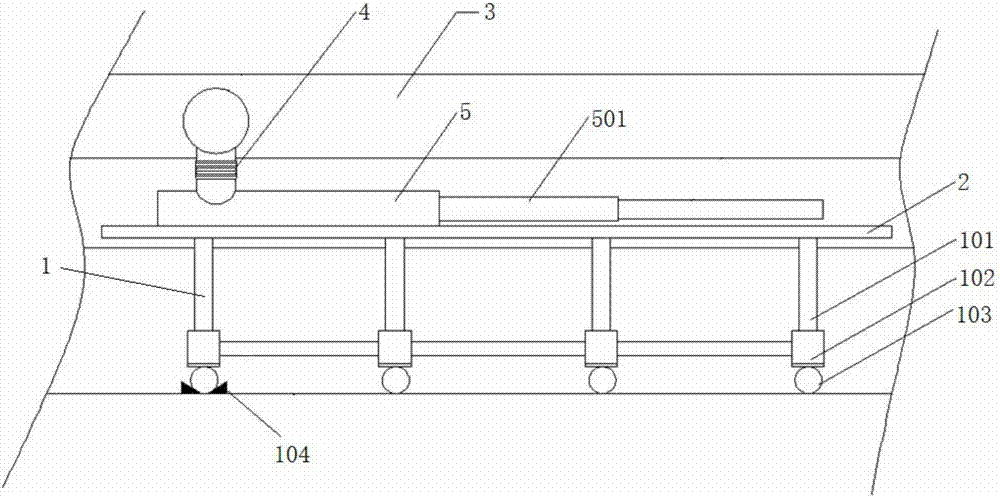
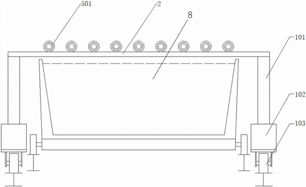
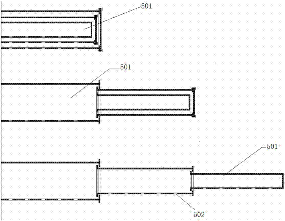
[0084] A multi-degree-of-freedom blowing device for sintering includes a pillar 1, a support 2, a fuel delivery pipe 3, a fuel branch pipe 4, a blowing pipe 5 and a sintering machine 8. The pillars 1 are located on both sides of the sintering machine 8, and the support 2 is arranged above the sintering machine. The bracket 2 is arranged on the pillar 1 . The fuel delivery pipe 3 is connected to the fuel branch pipe 4 . The injection pipe 5 is connected to the fuel branch pipe 4 . The blowing pipe 5 is arranged on the support 2 . The blowing pipe 5 is a two-section blowing sleeve 501 . The blowing sleeve 501 adopts the structure of a telescopic sleeve. The blowing sleeve 501 is provided with blowing holes 502 .

[0085] One side of the fuel delivery pipe 3 is provided with 20 fuel branch pipes 4 . One side of the fuel branch pipe 4 is provided with 10 injection pipes 5 .

Embodiment 2

[0087] Embodiment 1 is repeated, except that the fuel branch pipe 4 and the fuel delivery pipe 3 are connected through a metal hose 401 . The lower end of the pillar 1 is provided with a traveling wheel 103 .

Embodiment 3

[0089] Embodiment 1 is repeated, except that the fuel branch pipe 4 and the fuel delivery pipe 3 are connected through a metal hose 401 . The pillar 1 includes a fixed support leg 101 and a lifting device 102 . The lifting device 102 is an electric screw type lifting device.


PUM

PropertyMeasurementUnit
porosityaaaaaaaaaa

Abstract

A multi-degree of freedom injection device for sintering comprises stand columns (1), a rack (2), a fuel conveying pipe (3), a fuel branch pipe (4), an injection-blow pipe (5) and a sintering machine trolley (8), wherein the stand columns (1) are arranged on two sides of a sintering machine (8); the rack (2) is mounted over the sintering machine trolley (8); the fuel branch pipe (4) is connected with the fuel conveying pipe (3); the injection-blow pipe (5) is connected with the fuel branch pipe (4); the injection-blow pipe (5) is arranged on the rack (2); the injection-blow pipe (5) is an injection-blow casing pipe (501) having two or more sections; the injection-blow casing pipe (501) is in a telescopic casing pipe structure; and an injection-blow hole (502) is formed in the injection-blow casing pipe (501). The intelligent injection-blow device and an operation method for the same can change according to changes of work conditions such as material types, material surface height and sintering machine speed; deficiencies of the prior art can be remedied; and production stability, economic property and safety can be improved.

Description

technical field [0001] The invention relates to a blowing device and a using method thereof, in particular to a multi-degree-of-freedom blowing device and a using method thereof, belonging to the field of sintering. Background technique [0002] The sintering process is a key link in the ironmaking process. Its principle is to mix various powdery iron-containing raw materials with an appropriate amount of fuel and flux, add an appropriate amount of water, mix and pelletize the material on the sintering equipment to make the material A series of physical and chemical changes, sintered into blocks, which are sent to the blast furnace for the next step. [0003] In order to reduce the coke ratio and smelting cost of blast furnace ironmaking, blast furnaces often require high strength and high reducibility for sinter. In the sintering process, the sintered ore is generally required to have high strength, high yield, low return rate, and low fuel consumption. High-strength and ...

Claims


Application Information

Patent Timeline
Patent Type & Authority Applications(China)
IPC IPC(8): F23D14/00F23D14/46C22B1/16
CPCF23D14/00F23D14/46F27D99/0033C22B1/16F23D2900/21F27M2003/04F27D2099/004
Inventor 周浩宇贺新华
Owner ZHONGYE-CHANGTIAN INT ENG CO LTD
Why Eureka
Try Eureka