
Transparent display panel and manufacturing method thereof

A technology for a transparent display panel and a manufacturing method, applied in the fields of nonlinear optics, instruments, optics, etc., which can solve the problems of reduced light transmittance, difficulty in improving dimming ability, afterimage, etc., and achieve good display contrast and good display image quality , the effect of high structural transmittance

Inactive Publication Date: 2017-11-17
NANJING BOE DISPLAY TECH CO LTD
View PDF6 Cites 2 Cited by
  • Summary
  • Abstract
  • Description
  • Claims
  • Application Information

AI Technical Summary

Problems solved by technology

[0003] The existing transparent display technology is that the use of polarizers will reduce the light transmittance, and the second is to add dye molecules to the liquid crystal molecules. When the dye molecules are added, ions will be generated due to the UV irradiation process during the cell formation, and the voltage retention rate will be reduced. (voltage holding ratio, VHR), it is easy to appear afterimages and other problems that reduce the display quality when displaying
When displaying, it is easy to have afterimages and other problems that reduce the display quality. In addition, the content of the added dye molecules is limited and the dimming ability is limited, so it is difficult to improve the contrast (if the content is too high, it will be easy to precipitate, and the driving voltage will increase accordingly)

Method used


Image

  • Transparent display panel and manufacturing method thereof
  • Transparent display panel and manufacturing method thereof

Examples


Embodiment Construction

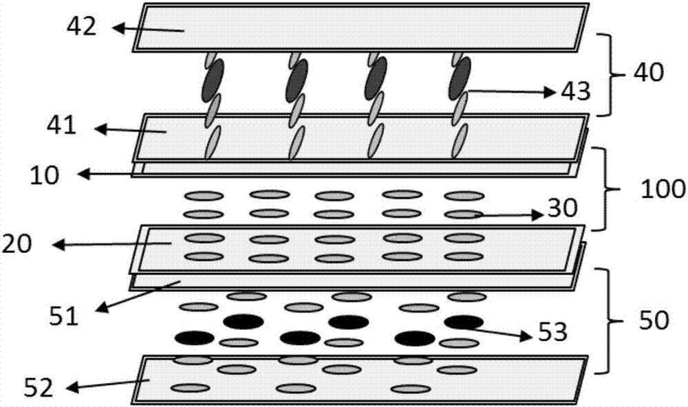
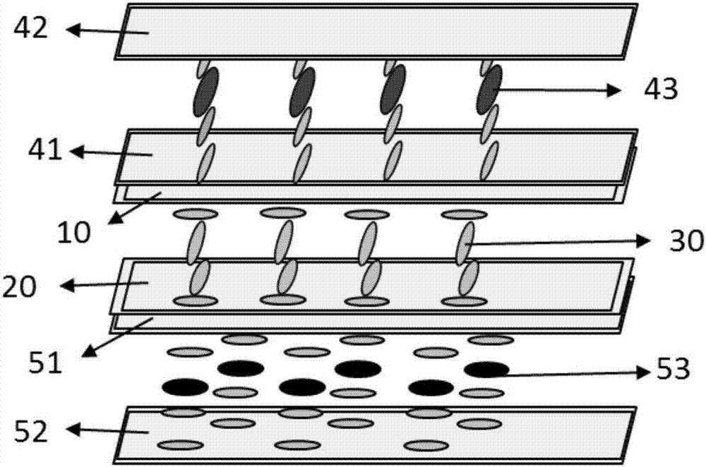
[0022] figure 1 and figure 2 Shown is a schematic structural view of the transparent display panel of the present invention.

[0023] The transparent display panel includes: a first substrate 10 , a first alignment film located on the inner surface of the first substrate 10 , a second substrate 20 opposite to the first substrate 10 , and a second alignment film located on the inner surface of the second substrate 20 , the second liquid crystal molecules 30 located between the first alignment mode and the second alignment mode, the third substrate 41 located outside the first substrate 10 and attached to the first substrate 10 , the third substrate 41 located on the inner surface of the third substrate 41 Three alignment modes, a fourth substrate 42 opposite to the third substrate 41, a fourth alignment mode located on the inner surface of the fourth substrate 42, a first dye molecule sandwiched between the third alignment mode and the fourth alignment mode, and The first li...


PUM


Abstract

The invention provides a transparent display panel and a manufacturing method thereof. The transparent display panel includes a first dye and liquid crystal absorption layer, a third dye and liquid crystal absorption layer and a second display layer which is located between the first dye and liquid crystal absorption layer and the third dye and liquid crystal absorption layer; first dye molecules and first liquid crystal molecules are arranged in the first dye and liquid crystal absorption layer, and the long axis directions of the first dye molecules are parallel to those of the first liquid crystal molecules; third dye molecules and third liquid crystal molecules are arranged in the third dye and liquid crystal absorption layer, and the long axis directions of the third dye molecules are parallel to those of the third liquid crystal molecules; certain included angles are formed between the long axis directions of the first dye molecules and the long axis directions of the third dye molecules. The transparent display panel adopts a double-layer structure containing the dye and liquid crystal molecules, the transmittance is high, the dark-state brightness is low, and the contrast ratio is high; meanwhile, the VHR of a display area in the second layer is high, the quality of image displaying is good, so that the gray-level is capable of being adjusted to reach a good display contrast ratio, and the transparent display panel has a relatively high response speed.

Description

technical field [0001] The invention belongs to the technical field of liquid crystal display panels, and in particular relates to a transparent display panel and a manufacturing method thereof. technical background [0002] The transparent display allows users to clearly see the background behind the display when watching the display, giving consumers a refreshing feeling. It can be applied to windows, car windows, windshields, and commercial advertisement displays, and its application range is becoming wider and wider. [0003] The existing transparent display technology is that the use of polarizers will reduce the light transmittance, and the second is to add dye molecules to the liquid crystal molecules. When the dye molecules are added, ions will be generated due to the UV irradiation process during the cell formation, and the voltage retention rate will be reduced. (voltage holding ratio, VHR), it is prone to problems such as afterimages and other degradation of displ...

Claims


Application Information

Patent Timeline
Patent Type & Authority Applications(China)
IPC IPC(8): G02F1/1347G02F1/1333
Inventor 黄善兴陈钢王志军张卫锴
Owner NANJING BOE DISPLAY TECH CO LTD
Learn More