Dynamic control method of edge light LED (Light Emitting Diode) backlight

A technology of LED backlight and dynamic control, applied in static indicators, instruments, etc., can solve the problems of less obvious power consumption saving effect of backlight source and no effective use of LED grouping controllability, so as to reduce the amount of calculation, To achieve the effect of convenience and reduce side light leakage

Inactive Publication Date: 2014-07-23
BOE TECH GRP CO LTD
View PDF4 Cites 0 Cited by
  • Summary
  • Abstract
  • Description
  • Claims
  • Application Information

AI Technical Summary

Problems solved by technology

Although this method is convenient to implement, it does not effectively utilize the group controllability of LEDs, and the saving effect of backlight power consumption is not obvious

Method used


Image

  • Dynamic control method of edge light LED (Light Emitting Diode) backlight
  • Dynamic control method of edge light LED (Light Emitting Diode) backlight
  • Dynamic control method of edge light LED (Light Emitting Diode) backlight

Examples


Embodiment Construction

[0018] In order to enable those skilled in the art to better understand the technical solution of the present invention, the dynamic control method of the side-light LED backlight provided by the present invention will be described in detail below with reference to the accompanying drawings. Among them, the same components are denoted by the same reference numerals, and descriptions thereof will be omitted to avoid redundancy.

[0019] In this embodiment, the "gray value" is an integer selected from 0-255 (including 0 and 255).

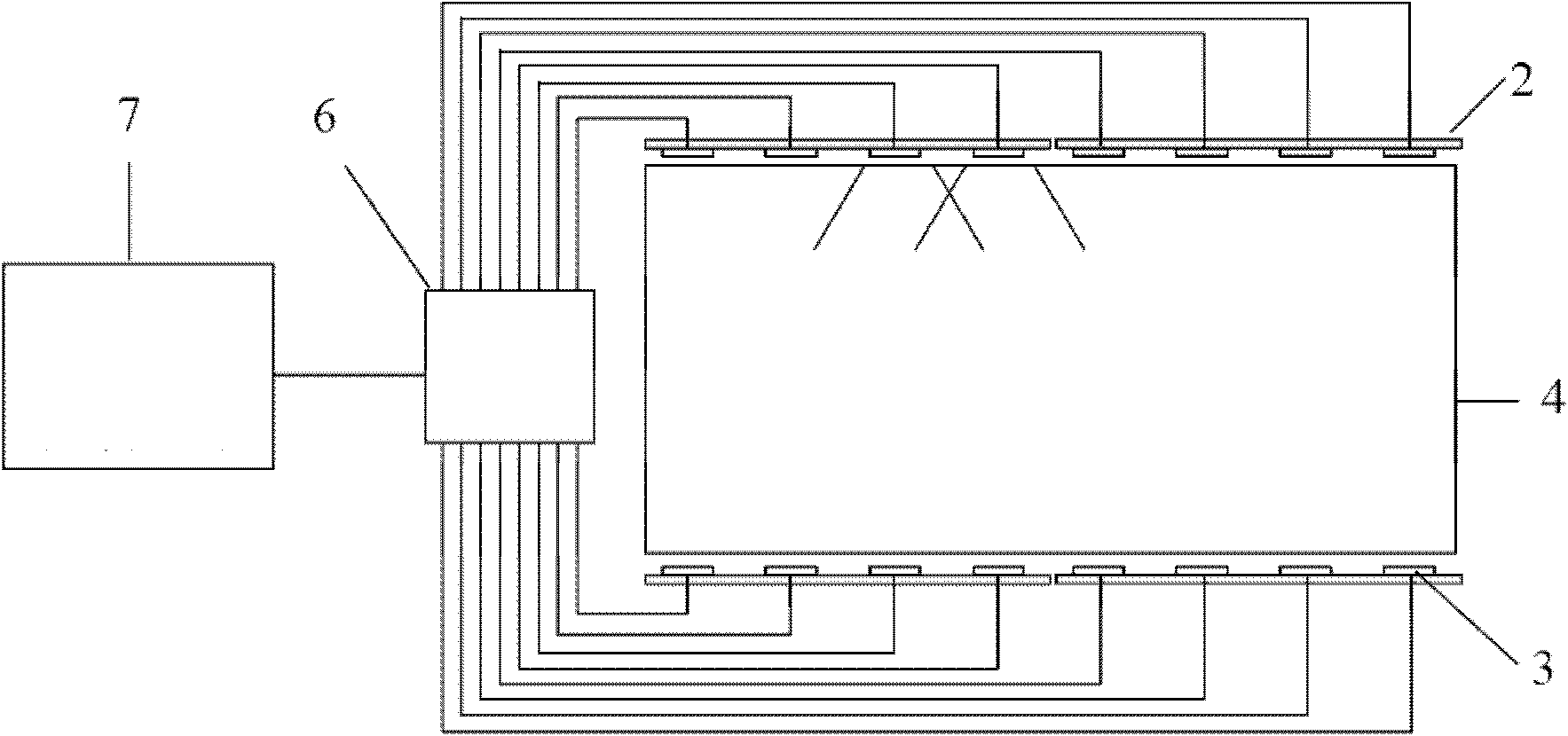
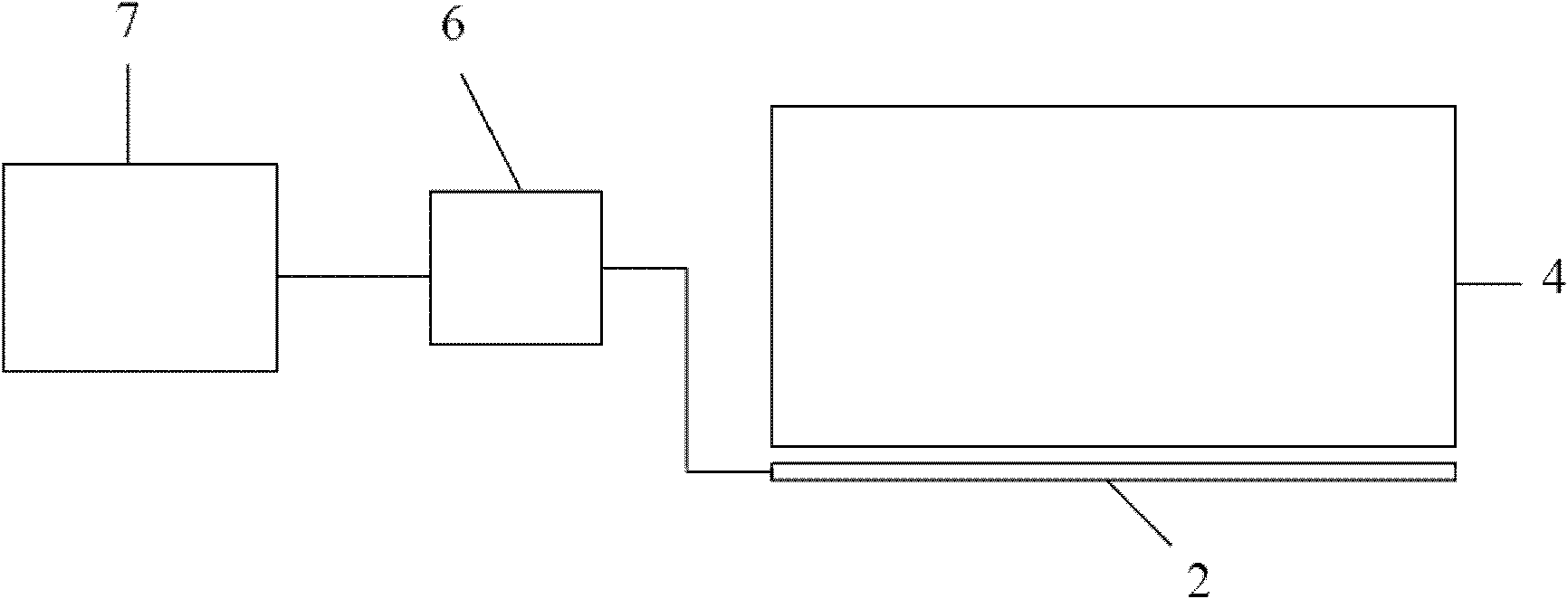
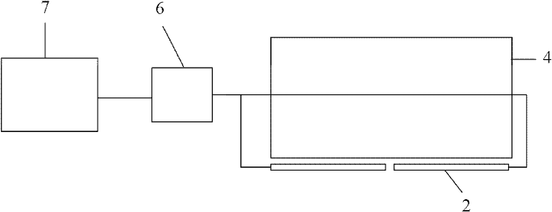
[0020] figure 1 is a schematic diagram of an edge-lit LED backlight. Such as figure 1 As shown, the edge-lit LED backlight includes a light guide plate 4 and at least one LED light bar 2 arranged around the light guide plate. Specifically, the LED light bar 2 can be located on one side of the backlight or on both sides of the backlight. , three sides or four sides, the LED light bar 2 on each side can be one, also can be two or more. For example, ...


PUM


Abstract

The invention discloses a dynamic control method of edge light LED (Light Emitting Diode) backlight used for liquid crystal screens. The edge light LED backlight comprises a plurality of groups of LEDs. The method comprises the following steps of: obtaining grayscale data of an original image of a current frame in video signals; obtaining first optimization brightness data of each group of LEDs according to the grayscale data of the original image of the current frame and data of a contribution rate of each group of LEDs to backlight; performing histogram statistics of the number of grayscale pixels to the grayscale data of the original image of the current frame, and determining a whole threshold grayscale according to the result of the histogram statistics; obtaining second optimization brightness data of each group of LEDs according to the first optimization brightness data of each group of LEDs and the whole threshold grayscale; and regulating the data of the original image of the current frame according to the second optimization brightness data of each group of LEDs, and generating output image data of the current frame. According to the method, the visual effect of a screen is guaranteed. Additionally, the power consumption of the backlight is greatly reduced, and the contrast of the screen is increased.

Description

technical field [0001] The invention belongs to the field of LED backlight sources and relates to a dynamic control method for side-light LED backlight sources used for liquid crystal screens. Background technique [0002] In recent years, traditional cathode ray tubes (CRTs) have been gradually replaced by liquid crystal displays (LCDs) due to their shortcomings such as bulky size, high radiation, and high power consumption. The backlight source of the current LCD display screen is mainly divided into two types according to the material of the light source: a cold cathode fluorescent tube (CCFL) backlight source and a light emitting diode (LED) backlight source. CCFL backlight has the advantages of high luminous efficiency, but it contains mercury vapor that is harmful to human body and environment, and its color reproduction is poor, the driving circuit is complicated, and a driving voltage of thousands of volts is required; LED backlight has good color reproduction and wi...

Claims


Application Information

Patent Timeline
Patent Type & Authority Patents(China)
IPC IPC(8): G09G3/34G09G3/36
Inventor 赵星星蒋文杰张丽蕾
Owner BOE TECH GRP CO LTD
Why Eureka
Try Eureka