Achieving method for dynamically controlling slow light of photonic crystal

A photonic crystal, dynamic control technology, applied in the optical field, can solve the problems of narrow slow light bandwidth, large group velocity dispersion, inability to dynamically change the refractive index position and group velocity, etc., achieve low group velocity, large flat bandwidth, stable slow light effect

Active Publication Date: 2017-11-17
QINGDAO UNIV
View PDF3 Cites 5 Cited by
  • Summary
  • Abstract
  • Description
  • Claims
  • Application Information

AI Technical Summary

Problems solved by technology

[0005] The present invention aims to solve the problem that the bandwidth of slow light in the existing photonic crystal-based slow light structure is too narrow, the group velocity dispersion is too large, and the optimal broadband slow light group refractive index position and group velocity supported after the preparation of the slow light waveguide cannot be solved. Dynamically Changing Problems

Method used


Image

  • Achieving method for dynamically controlling slow light of photonic crystal
  • Achieving method for dynamically controlling slow light of photonic crystal
  • Achieving method for dynamically controlling slow light of photonic crystal

Examples


example 1

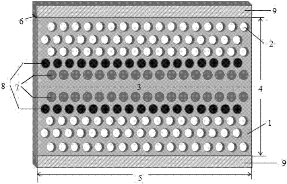
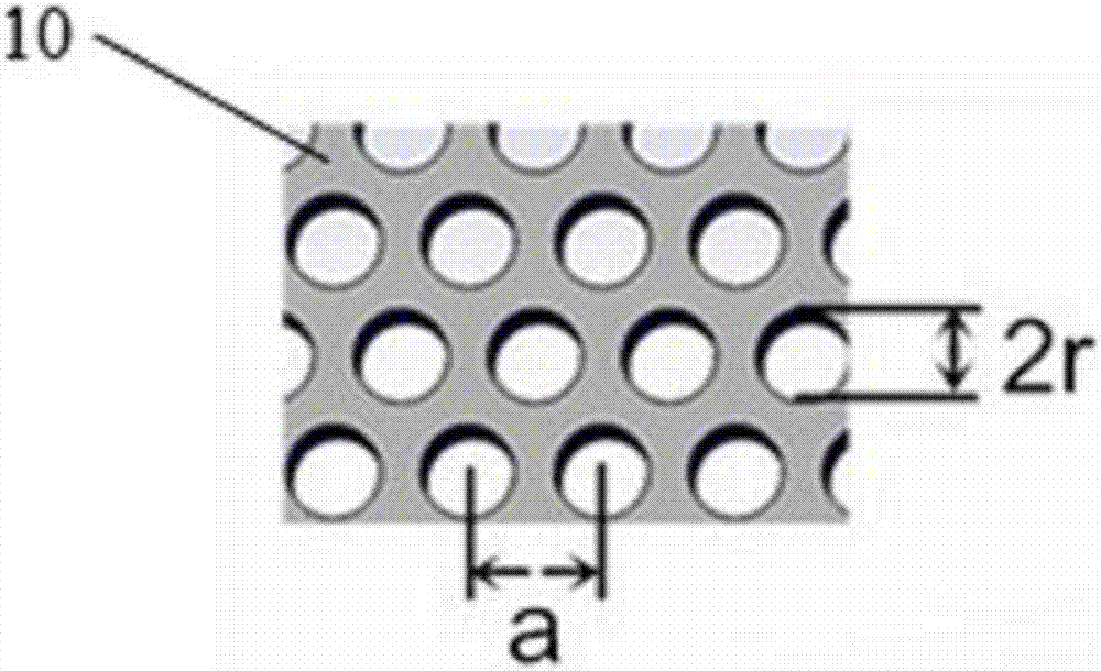
[0038] Construct a low-scattering photonic crystal slow light waveguide device for the purpose of obtaining a higher group refractive index, take the lattice constant a=330nm of the triangular lattice arranged by air holes, and take 0.328a=108.24nm for the air hole radius r, and the waveguide The air holes in the first row on both sides are filled with ordinary organic polymers 1 =1.74, the electro-optic coefficient of hole filling in the second row γ 33 =180pm / V,n poly = 1.6 photoorganic polymer polystyrene, applied voltage 120V, after reaching stability, the refractive index n of the organic polymer polystyrene in the second row of holes 2 Decrease to obtain the average group refractive index of the flat region of the device The flat slow light region appears near the third communication window of the optical fiber at 1530-1536.3nm, with a bandwidth of 6.3nm (group refractive index variation range n g within ±10%), the maximum group velocity dispersion coefficient β in t...

example 2

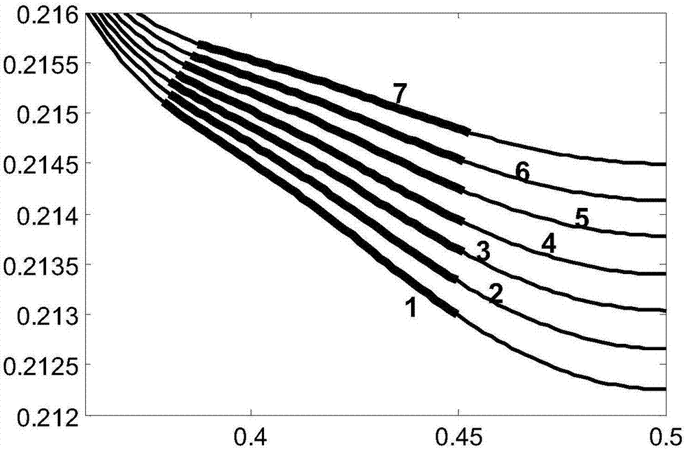
[0040] Construct a low-scattering photonic crystal slow light waveguide device for the purpose of obtaining a wider bandwidth, take the external voltage as 0V, and the second row of organic polymer refractive index n 2 = 1.6, other conditions are the same as Example 1, and the average group refractive index of the flat broadband slow light region of the device is obtained Flat slow light appears in the 15.2nm range from 1534.1nm to 1549.3nm (group refractive index variation range n g Within ±10%, it is regarded as the equilibrium unchanged, such as image 3 , 4 , shown in curve 1 in 5), the maximum group velocity dispersion coefficient β in the flat band 2 2 / mm, the normalized delay-bandwidth product reaches 0.3355, wider bandwidth, lower dispersion, and stronger delay storage capacity.

example 3

[0042] Construct a broadband low-dispersion photonic crystal slow light waveguide device in the low-frequency (long-wave) terahertz region, take the lattice constant a of the triangular lattice arranged with air holes = 64 μm, take the radius of the circular air holes as 0.328a = 20.99 μm, the waveguide The air holes in the first row on both sides are filled with ordinary organic polymers 1 =1.74, the electro-optic coefficient of hole filling in the second row γ 33 =180pm / V,n poly = 1.6 electro-optic organic polymer, the two sides of the waveguide are applied with an external voltage of 20V, and after the slow light is stably transmitted, the refractive index of the organic polymer in the second row of holes is reduced to n 2 =1.53, to obtain the average group refractive index in the slow light flat region Flat slow light appears in the 2.6μm range from 297.4μm to 300.0μm (frequency about 1THz) (group refractive index variation range n g within ±10%), the maximum group vel...


PUM

PropertyMeasurementUnit
refractive indexaaaaaaaaaa

Abstract

The invention discloses an achieving method for dynamically controlling slow light of a photonic crystal. The method comprises the steps that a, qualitative parameters are initiated; b, under the condition of high group refractive index and low dispersion, a slow light waveguide device has a flat and wide-band slow light effect, the speed of a slow light group with the effect varies according to control of an impressed voltage in a large range, and thus the flat and wide-band slow light effect is obtained; c, a slow light effect with wide band and low dispersion is obtained under the context that ng is kept stable in the range that the absolute value of delta ng is smaller than or equal to 10%; d, the low dispersion characteristic of the slow light and the relation between the bandwidth and group refractive index are obtained; e, the refractive index change of an organic polymer with an electrooptical effect is mainly affected by a Pockels effect, and the variable amount of the refractive index is dependent on the secondary-order magnetic susceptibility of a material; f, under the effect of a light field local area, the valid secondary-order polarizability of the organic polymer is effectively improved. The achieving method solves the problems that the refractive index position and the group speed of a supported optimal wide-band slow light group cannot dynamically vary after preparation of slow light waveguide is completed.

Description

technical field [0001] The invention relates to the field of optical technology, in particular to a method for realizing slow light of a dynamically controlled photonic crystal. Background technique [0002] The slow light effect means that the transmission of electromagnetic waves has a speed 3×10 faster than that of light in vacuum. 8 The m / s group velocity is much lower, and it can be widely used in optical delay lines, all-optical buffers, optical modulators, optical switches, and strengthening the interaction between light and matter. The slow light structure of photonic crystals, because of its small and compact structure, easy integration, easy coupling and matching with optical fiber systems, small transmission loss, and room temperature operation, can be flexibly designed to control slow light effects and other characteristics through structure and materials. Photonic crystal slow light It has unparalleled advantages in the application of all-optical communication ...

Claims


Application Information

Patent Timeline
Patent Type & Authority Applications(China)
IPC IPC(8): G02F1/365G02B6/122
CPCG02B6/1225G02F1/365
Inventor 李长红江永春闫崇庆
Owner QINGDAO UNIV
Why Eureka
Try Eureka