
Corner forming machine

A molding machine and corner technology, applied in packaging/dipping, electrical components, inductor/transformer/magnet manufacturing, etc., can solve the problems of low work efficiency and low yield rate, improve work efficiency and yield rate, and have a high degree of automation Effect

Active Publication Date: 2017-11-17
GUANGZHOU JINGCHENGDA PRECISION MACHINERY CO LTD
View PDF3 Cites 4 Cited by
  • Summary
  • Abstract
  • Description
  • Claims
  • Application Information

AI Technical Summary

Problems solved by technology

Inductors need to be packaged during the mass production process; the inductance body product after molding and curing by the press is a contiguous structure, and the inductance packaging process generally includes cutting the contiguous structure into a single structure, and then folding the electrodes on both sides upwards bend; cut into a single structure of the inductor such as Figure 8 As shown, the horizontal position of the electrode 102 towards both ends, the structure after the packaging is completed is as follows Figure 9 As shown, the electrode 102 is close to the edge of the inductor 101; the bending process of the inductor in the prior art is generally done manually, and its work efficiency and yield are low.

Method used


Image

  • Corner forming machine
  • Corner forming machine
  • Corner forming machine

Examples


Embodiment 1

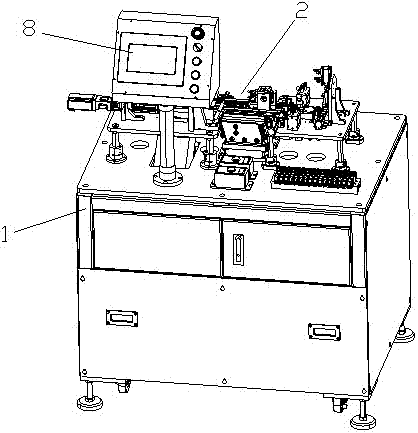
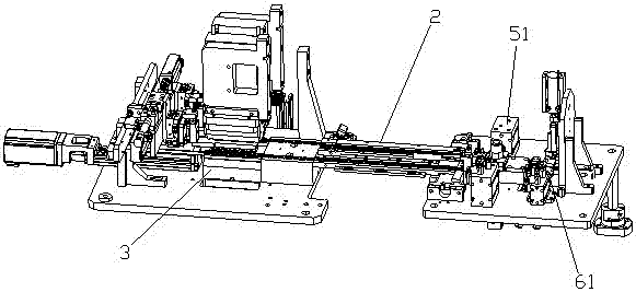
[0031] Such as figure 1 , 2 The shown corner forming machine includes a body 1, and the body 1 is provided with an inductive body product conveying line 2; the inductive body product conveying line 2 is sequentially provided with:

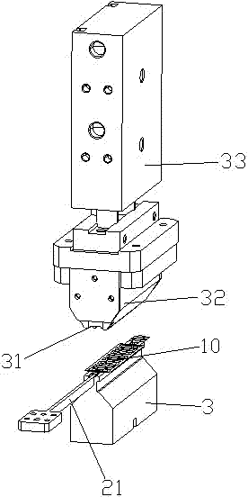
[0032] The preliminary cutting mechanism, the preliminary cutting mechanism includes the lower knife mold 3 and the upper cutting knife 31, and the described preliminary cutting mechanism is used to cut and remove the frame of the edge of the continuous-piece inductive body product to form a single piece with horizontal edges on both sides. The inductance body product 10 of the electrode 11, the described contiguous type inductance body product is placed on the lower die;

[0033] U-bending mechanism, the U-bending mechanism includes a limit pressure block 4 arranged on the upper part of the inductance product 10 and a lifting and bending device. The pressure wheel 41 is used to bend the horizontal electrode 11 of the inductance product 10 upwar...

Embodiment 2

[0038] Such as figure 1 , 2 The shown corner forming machine includes a body 1, and the body 1 is provided with an inductive body product conveying line 2; the inductive body product conveying line 2 is sequentially provided with:

[0039] The preliminary cutting mechanism, the preliminary cutting mechanism includes the lower knife mold 3 and the upper cutting knife 31, and the described preliminary cutting mechanism is used to cut and remove the frame of the edge of the continuous-piece inductive body product to form a single piece with horizontal edges on both sides. The inductance body product 10 of the electrode 11, the described contiguous type inductance body product is placed on the lower die;

[0040] U-bending mechanism, the U-bending mechanism includes a limit pressure block 4 arranged on the upper part of the inductance product 10 and a lifting and bending device. The pressure wheel 41 is used to bend the horizontal electrode 11 of the inductance product 10 upwar...


PUM


Abstract

The invention relates to a corner forming machine. The corner forming machine comprises a machine body, wherein the machine body is provided with an inductor body conveyor line; the inductor body conveyor line is provided with a primary trimming mechanism, a bent U mechanism, a refined trimming mechanism and a pressing mechanism in sequence, wherein the primary trimming mechanism comprises a lower cutting die and an upper trimming cutter; the bent U mechanism is used for bending the electrode of an inductor body product in the horizontal upwards into the vertical direction, so that the inductor body product is of a U-shaped structure; the refined trimming mechanism is used for trimming the length of the electrode into an accurate length; and the pressing mechanism is used for pressing the electrode inwards, so that the electrode clings to the upper surface of the inductor body product. The corner forming disclosed by the invention is high in automation degree, and the working efficiency and yield are improved.

Description

technical field [0001] The invention relates to the field of inductor processing, in particular to an angle forming machine. Background technique [0002] Inductor is a component that can convert electrical energy into magnetic energy and store it. Inductors need to be packaged during the mass production process; the inductor product after molding and curing by the press is a contiguous structure, and the inductance packaging process generally includes cutting the contiguous structure into a single structure, and then folding the electrodes on both sides upwards bend; cut into a single structure of the inductor such as Figure 8 As shown, the horizontal position of the electrode 102 towards both ends, the structure after the packaging is completed is as follows Figure 9 As shown, the electrode 102 is closely attached to the edge of the inductor 101; the bending process of the inductor in the prior art is generally done manually, and its work efficiency and yield are low. ...

Claims


Application Information

Patent Timeline
IPC IPC(8): H01F41/00
CPCH01F41/005
Inventor 杨兴鸿杨仕飞汪国勇吴超超
Owner GUANGZHOU JINGCHENGDA PRECISION MACHINERY CO LTD
Learn More