Heat superconductive panel fin radiator with fins on surface thereof

A technology of thermal superconductivity and heat sink, applied in the field of heat transfer, can solve the problems that aluminum heat sinks cannot meet the heat dissipation requirements of high heat flux density and high-power modules, and achieve good work adaptability, solve heat dissipation requirements, and small volume effects

Active Publication Date: 2017-11-17
ZHEJIANG JIAXI TECH CO LTD
View PDF8 Cites 8 Cited by
  • Summary
  • Abstract
  • Description
  • Claims
  • Application Information

AI Technical Summary

Problems solved by technology

[0004] In view of the above-mentioned shortcomings of the prior art, the object of the present invention is to provide a thermal superconducting plate-fin radiator with fins on the surface, which is used to solve the problem that the aluminum radiator in the prior art cannot meet the high heat flow requirements. The problem of heat dissipation requirements of high-density high-power modules

Method used


Image

  • Heat superconductive panel fin radiator with fins on surface thereof
  • Heat superconductive panel fin radiator with fins on surface thereof
  • Heat superconductive panel fin radiator with fins on surface thereof

Examples


Embodiment 1

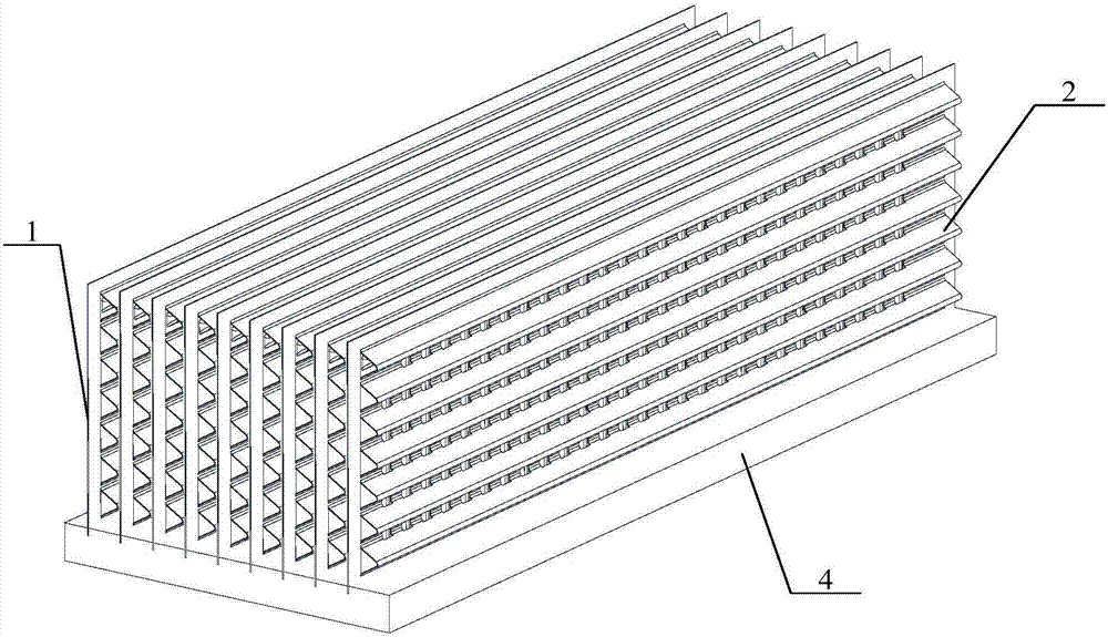
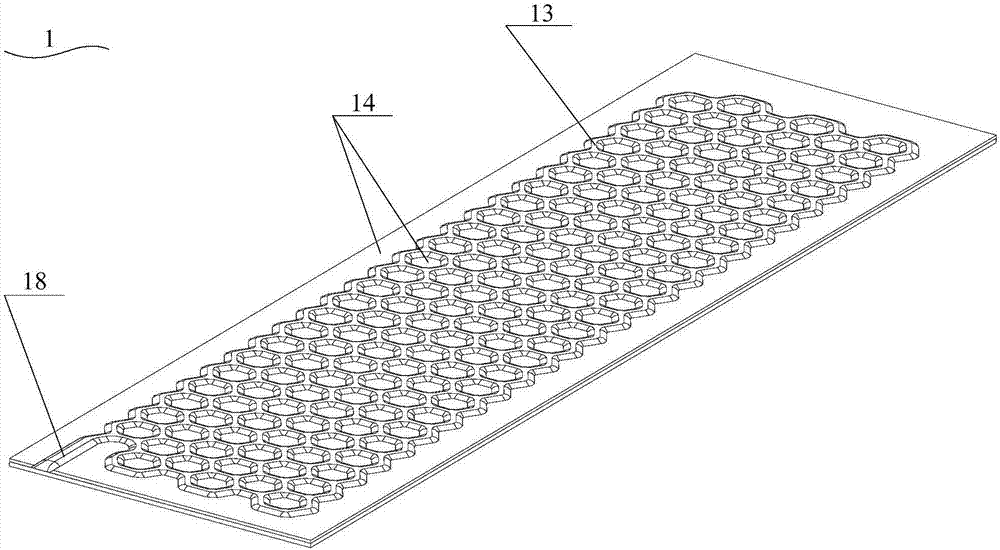
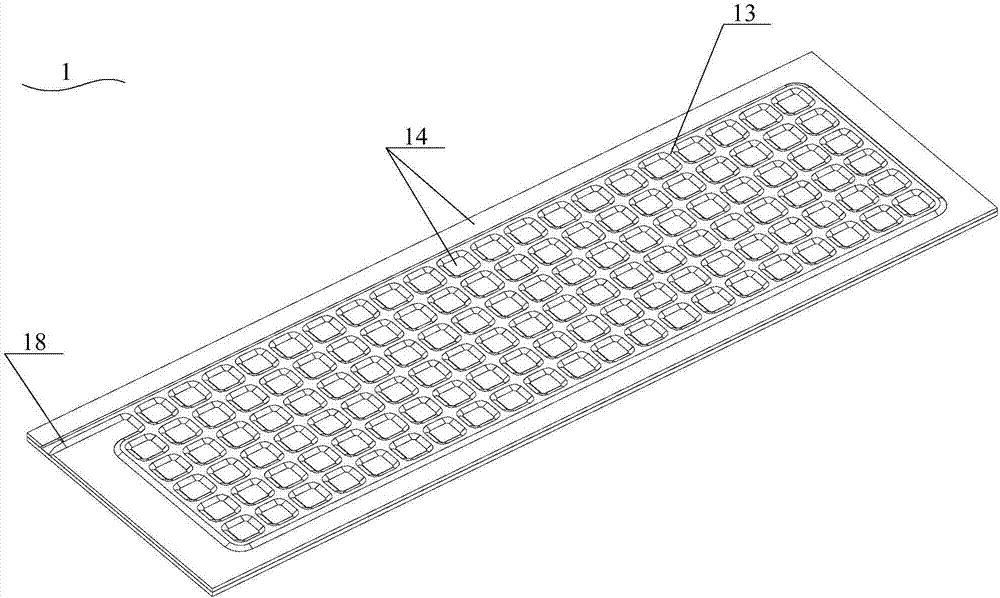
[0074] see Figure 1 to Figure 12 , the present invention provides a thermal superconducting plate-finned radiator with fins on the surface, the thermal superconducting plate-finned radiator with fins on the surface comprising: a radiator substrate 4; Conductive heat dissipation plate 1, a plurality of thermal superconducting heat dissipation plates 14 are inserted in parallel on the surface of the heat sink substrate; a thermal superconducting circuit 13 is formed in the thermal superconducting heat dissipation plate 1, and the thermal superconducting conduit The road 13 is a closed pipeline, and the thermal superconducting pipeline is filled with a heat transfer working medium (not shown); a heat dissipation fin structure 2, and the heat dissipation fin structure 2 is located at least on the thermal superconducting heat dissipation plate 1 One surface; the heat dissipation fin structure 2 includes at least one heat dissipation fin 21 extending in a wave shape in a direction ...

Embodiment 2

[0095] This embodiment also provides a thermal superconducting plate-finned heat sink with fins on the surface. The structure of the thermal superconducting component described in this embodiment is the same as that described in Embodiment 1. The structures of thermal superconducting plate-finned heat sinks are roughly the same, and the difference between the two is that in Embodiment 1, the heat dissipation fin structure 2 includes a first heat dissipation fin 22, and the first heat dissipation fin 22 is located at One surface of the thermal superconducting heat dissipation plate 1; and in this embodiment, the heat dissipation fin structure 2 includes two first heat dissipation fins 22, and the two first heat dissipation fins 22 are respectively located at the The two opposite surfaces of the thermal superconducting radiator plate 1.

Embodiment 3

[0097] see Figure 13 , this embodiment also provides a thermal superconducting plate-finned heat sink with fins on the surface, the structure of the thermal superconducting component described in this embodiment is the same as that described in Embodiment 1 that the surface is provided with fins The structure of the thermal superconducting plate finned heat sink is roughly the same, the difference between the two is: in the first embodiment, the heat dissipation fin structure 2 includes a first heat dissipation fin 22, and the first heat dissipation fin 22 Located on one surface of the thermal superconducting heat dissipation plate 1; and in this embodiment, the heat dissipation fin structure 2 includes a first heat dissipation fin 22, and the first heat dissipation fin 22 is located in two adjacent between the thermal superconducting heat sinks 1, and simultaneously fixed on the surfaces of two adjacent thermal superconducting heat sinks 1, that is, the first raised structur...


PUM


Abstract

The invention provides a heat superconductive panel fin radiator with fins on the surface thereof. The radiator herein includes: a radiator substrate; a plurality of heat superconductive heating panels which are parallelly disposed at intervals on the surface of the radiator substrate; each heat superconductive heating panel is provided with a heat superconductive pipeline which is formed therein, and the heat superconductive pipeline is a closed pipeline which is filled with a heat conductive working medium; a radiating fin structure which is disposed on at least one surface of each heat superconductive heating panel; the radiating fin structure includes at least one radiating fin which extends in wave form along the direction in parallel to the surface of the heat superconductive heating panel. According to the invention, the heat superconductive panel fin radiator herein has the characteristics of high fin efficiency, large heat exchange area per unit volume, strong radiating capability, small size, light weight, flexible and various appearance and structure, low cost and small radiator substrate. The heat superconductive panel fin radiator herein can deploy devices with large power, is suitable to lower temperature environment of alpine regions in winter, and addresses the anti-freezing problem of heat pipes and water-cooled radiators.

Description

technical field [0001] The invention belongs to the technical field of heat transfer, in particular to a thermal superconducting plate-finned heat sink with fins on the surface. Background technique [0002] With the rapid development of power electronics technology, the requirements for modularization, integration, lightweight, low cost and high reliability are getting higher and higher. Therefore, in solar inverters, uninterruptible power supplies (UPS), charging piles, power MosFET (metal oxide semiconductor field effect transistor), Diode (diode), IGBT ( insulated gate bipolar transistors) and other power devices. As the integration of these power components is getting higher and higher, the power density is also increasing, and the heat generated by themselves is also increasing during work, and the heat flux density is getting higher and higher. The conduction and dissipation of heat will cause the temperature of the chip in the power device to rise, which will cause...

Claims


Application Information

Patent Timeline
Patent Type & Authority Applications(China)
IPC IPC(8): H01L23/367H01L23/373H01L23/427H01L23/467
CPCH01L23/3672H01L23/3735H01L23/427H01L23/467
Inventor 仝爱星斯奕超曾巧
Owner ZHEJIANG JIAXI TECH CO LTD
Why Eureka
Try Eureka