
Miniaturized high-gain dual-band circularly-polarized antenna

A circularly polarized antenna and dual-band technology, which is applied to antennas, slot antennas, and devices that enable antennas to work in different bands at the same time, can solve the problem of increasing the production cost and difficulty of double-layer patches, increasing the complexity of the feeding network, Unfavorable antenna miniaturization and other issues

Pending Publication Date: 2017-11-17
GUILIN UNIV OF ELECTRONIC TECH
View PDF8 Cites 7 Cited by
  • Summary
  • Abstract
  • Description
  • Claims
  • Application Information

AI Technical Summary

Problems solved by technology

[0004] There are many ways to realize the miniaturization of the antenna, such as through the use of high dielectric constant materials, and slots of various shapes on the patch; in order to realize the circular polarization of the antenna, there is a single-feed method in terms of feeding methods And double-feed or multi-feed method, although double-feed and multi-feed can increase the circular polarization bandwidth, but it greatly increases the complexity of the feed network, which is not conducive to the miniaturization of the antenna; in order to obtain dual frequency bands, multiple Double-layer microstrip patch is used, but the double-layer patch increases the production cost and difficulty

Method used


Image

  • Miniaturized high-gain dual-band circularly-polarized antenna
  • Miniaturized high-gain dual-band circularly-polarized antenna
  • Miniaturized high-gain dual-band circularly-polarized antenna

Examples


Embodiment Construction

[0039] The present invention will be further described below in conjunction with the accompanying drawings and embodiments.

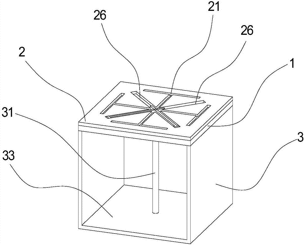
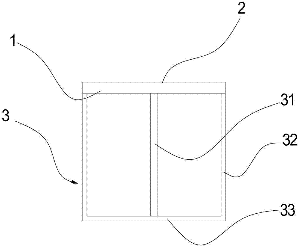
[0040] like Figure 1 to Figure 7 As shown, the miniaturized high-gain dual-band circularly polarized antenna of the present invention includes an insulating dielectric substrate 1, a radiator 2, and a U-shaped metal back cavity 3; the radiator 1 is printed on the insulating dielectric substrate in a planar shape the upper surface of 1;

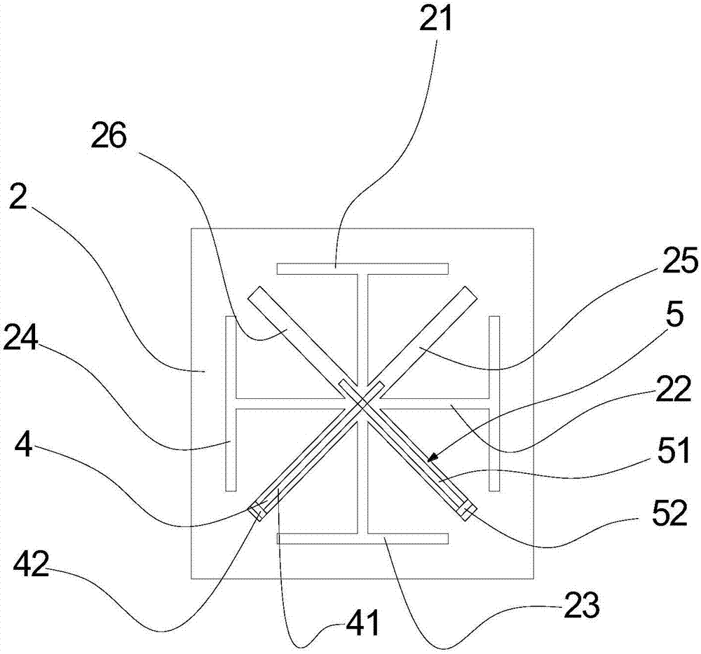
[0041] The radiator 1 is rectangular, and the radiator 1 is provided with first T-shaped slots 21 extending from the center of the radiator 1 to the four sides and uniformly distributed along the circumference of the circle centered on the center of the radiator 1. The second T-shaped slot 22, the third T-shaped slot 23 and the fourth T-shaped slot 24; the first T-shaped slot 21, the second T-shaped slot 22, the third T-shaped slot 23 and The fourth T-shaped slots 24 each include a transverse slot and a vertical slot, ...


PUM


Abstract

The invention discloses a miniaturized high-gain dual-band circularly-polarized antenna which is simple in structure and can realize miniaturization, dual frequency band, high gain and right-handed circular polarization, the bandwidth of the antenna is increased, and the gain of the antenna is improved. The miniaturized high-gain dual-band circularly-polarized antenna comprises an insulating medium substrate, a radiating body and a U-shaped metal back cavity; a first T-shaped slotted hole, a second T-shaped slotted hole, a third T-shaped slotted hole and a fourth T-shaped slotted hole which extend from the center of the radiating body to four sides of the radiating body and circumferentially uniformly distributed along a circle using the center of the radiating body as the center of the circle are formed in the radiating body; a first rectangular slotted hole and a second rectangular slotted hole are formed in the diagonal line of the radiating body, the first rectangular slotted hole is internally provided with a first T-shaped radiating body, and the second rectangular slotted hole is internally provided with a second T-shaped radiating body. By adopting the miniaturized high-gain dual-band circularly-polarized antenna, the requirement of military communication mobile phone antennas can be met, and the antenna is conveniently placed on the top of the communication mobile phone antenna, so that cover lifting is realized.

Description

technical field [0001] The invention relates to the technical field of antennas, in particular to a miniaturized high-gain dual-band circularly polarized antenna resonating in the uplink and downlink of the large S frequency band. Background technique [0002] It is known that the antenna plays an important role in transmitting and receiving electromagnetic waves in the wireless communication system. In addition to effectively radiating or receiving electromagnetic waves, it is also responsible for converting high-frequency current (guided wave energy) into wireless electromagnetic waves or converting wireless electromagnetic waves into High-frequency current (guided wave energy) work. Undoubtedly, the antenna plays the most basic and indispensable role, and its performance will directly affect the quality of the entire communication system. [0003] With the development of communication technology, the linear polarization method is far from meeting the work requirements, a...

Claims


Application Information

Patent Timeline
IPC IPC(8): H01Q13/10H01Q1/36H01Q1/38H01Q5/50
CPCH01Q1/36H01Q1/38H01Q5/50H01Q13/10Y02D30/70
Inventor 曹卫平周茶红李思敏蒋笑天
Owner GUILIN UNIV OF ELECTRONIC TECH
Learn More