Control device based on photovoltaic maximum power point tracking

A technology of maximum power point and control equipment, applied in photovoltaic power generation, control/regulation system, and regulation of electrical variables, etc., can solve the problems of reduced tracking accuracy, failure to consider dynamic coupling, reduced tracking efficiency, etc., and achieve the effect of convenient operation

Inactive Publication Date: 2017-11-17
泰州学院
View PDF10 Cites 3 Cited by
  • Summary
  • Abstract
  • Description
  • Claims
  • Application Information

AI Technical Summary

Problems solved by technology

There are some disadvantages: First, the two basic methods adopt a single open-loop structure for the output power, which does not take into account the dynamic coupling between the influencing factors, resulting in reduced tracking efficiency; second, the core controller does not have good reliability and is easy to program. The function can realize the programmable logic controller PLC of intelligent control, resulting in the reduction of tracking accuracy

Method used


Image

  • Control device based on photovoltaic maximum power point tracking
  • Control device based on photovoltaic maximum power point tracking
  • Control device based on photovoltaic maximum power point tracking

Examples


Embodiment

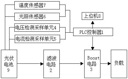
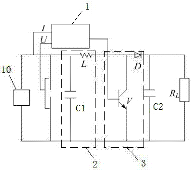
[0018] A control device based on photovoltaic maximum power point tracking, such as figure 1 As shown, it includes a sensor unit, a voltage detection sampling unit 4, a current detection sampling unit 5, a PLC controller 1 and an actuator, the actuator includes a Boost circuit 3 and a photovoltaic cell 9, and the photovoltaic cell 9 is connected to the Boost circuit 3 through a filter circuit 2, The Boost circuit 3 is connected in parallel with a load RL, the sensor unit includes a light sensor 6 and a temperature sensor 7, the light sensor 6 and the temperature sensor 7 are respectively arranged on the photovoltaic cell 9, and the light sensor 6 and the temperature sensor 7 are respectively connected to the input terminals of the PLC controller 1 , the output end of the PLC controller 1 is connected to the control end of the Boost circuit 3, and the input end of the PLC controller 1 is connected to the photovoltaic cell 9 through the voltage detection sampling unit 4 and the c...


PUM


Abstract

The invention provides a control device based on photovoltaic maximum power point tracking. The control device includes a sensor unit, a voltage detection sampling unit, a current detection sampling unit, a PLC controller and an execution mechanism. The execution mechanism includes a Boost circuit and a photovoltaic cell, the photovoltaic cell is connected with the Boost circuit through a filter circuit, the Boost circuit is in parallel with a load RL, the sensor unit includes a light sensor and a temperature sensor, the light sensor and the temperature sensor are arranged on the photovoltaic cell, the light sensor and the temperature sensor are connected to the input end of the PLC controller, the output end of the PLC controller is connected to the control end of a Boost converter, and the input end of the PLC controller is connected with the photovoltaic cell through the voltage detection sampling unit and the current detection sampling unit. The device acquires the detection data through temperature, light, voltage, and current, makes full use of the PLC programming advantages, programs the PLC procedures through an intelligent algorithm, and outputs the duty ratio of a Boost circuit switch tube, thereby realizing the MPPT intelligent tracking.

Description

technical field [0001] The invention relates to a control device based on photovoltaic maximum power point tracking. Background technique [0002] Since photovoltaic power generation technology can convert non-polluting and renewable solar energy into conveniently stored electrical energy, it has attracted increasing attention and attention in today's global energy shortage and serious environmental pollution. However, photovoltaic power generation has been facing the problem of low conversion efficiency. Maximum power tracking technology is currently recognized as an effective means to improve the efficiency of photovoltaic cells. [0003] At present, photovoltaic MPPT widely uses single-chip microcomputer as the core controller, and adopts two basic tracking methods: observation perturbation method and conductance incremental method. There are some disadvantages: First, the two basic methods adopt a single open-loop structure for the output power, which does not take into...

Claims


Application Information

Patent Timeline
Patent Type & Authority Applications(China)
IPC IPC(8): H02J7/35G05F1/67
CPCG05F1/67H02J7/35Y02E10/56
Inventor 夏华凤许胜付焕森曹健丁展周澄李元贵金丽君于晶晶
Owner 泰州学院
Why Eureka
Try Eureka