
Drinking water bucket cleaning device

A cleaning device and drinking water technology, applied in the direction of cleaning hollow objects, cleaning methods and utensils, chemical instruments and methods, etc., can solve the problems of low flushing efficiency, uneven flushing, high labor costs, etc., to achieve thorough cleaning and avoid stagnant water Excessive, high cleaning efficiency

Active Publication Date: 2017-11-21
贵州天壶泉饮品有限责任公司
View PDF6 Cites 8 Cited by
  • Summary
  • Abstract
  • Description
  • Claims
  • Application Information

AI Technical Summary

Problems solved by technology

[0002] At present, most domestic pure water processing enterprises have adopted highly automated assembly lines to produce bottled water. Due to the high manufacturing cost of water barrels, companies usually recycle and reuse water barrels. The recycled water barrels are filled again with pure water. Before watering, it is necessary to clean and disinfect the outer surface and the inside of the bucket. Nowadays, the common practice in the industry is to wash the inside of the bucket by the workers on the production line holding a high-pressure water gun. After the washing is completed, the water is poured manually. Come out, this method requires a lot of manual work, the washing efficiency is low and the labor cost is high
In addition, a high-pressure water gun is used to flush the inside of the bucket. Due to uneven flushing, sometimes there may be incomplete flushing inside the bucket, thus the cleaning quality cannot be guaranteed.

Method used


Image

  • Drinking water bucket cleaning device
  • Drinking water bucket cleaning device

Examples


Embodiment Construction

[0022] The present invention will be described in further detail below by means of specific embodiments:

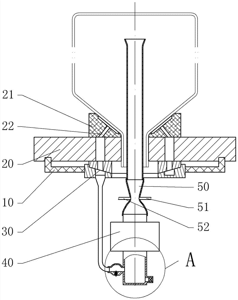
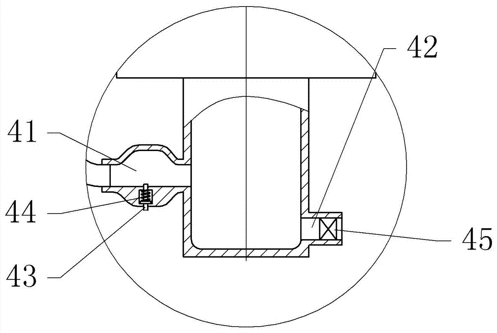
[0023] The reference signs in the accompanying drawings of the description include: seat body 10, turntable 20, suction cup 21, air hole 22, rotary joint 30, air pump 40, first air inlet 41, second air inlet 42, slide bar 43, return spring 44. Control valve 45, Venturi tube 50, particle spray pipe 51, water spray pipe 52.

[0024] The embodiment is basically as figure 1 , figure 2 Shown:

[0025] The drinking water bucket cleaning device of this embodiment includes a base body 10 , a motor and a turntable 20 rotatably connected to the base body 10 . The center of the turntable 20 is provided with a sleeve for the upper end of the water bucket to be inserted; the upper surface of the turntable 20 is fixed with a suction cup 21 that can cooperate with the water bucket, and the water bucket can be adsorbed on the turntable 20 through the suction cup 21, then the turntabl...


PUM


Abstract

The invention discloses a drinking water bucket cleaning device, and relates to the field of drinking water processing. The drinking water bucket cleaning device comprises a base, a motor and a rotary disc rotationally connected to the base. A casing pipe is arranged at the center of the rotary disc. A suction cup capable of being matched with the water bucket is fixed to the upper surface of the rotary disc. A water sprayer is arranged below the casing pipe and comprises a Venturi tube, a water spraying pipe with one end communicating with the throat part of the Venturi tube, and a particle spraying pipe with one end communicating with the throat part of the Venturi tube, a water tank and a particle storage box. The other end of the water spraying pipe stretches into the water tank, the other end of the particle spraying pipe stretches into the particle storage box, and the upper end of the Venturi tube is connected with a flow guiding pipe penetrating from the interior of the casing pipe, and the outer diameter of the flow guiding pipe ranges from 2 cm to 2.5 cm. The lower end of the Venturi tube is connected with an air pump, the exhaust end of the air pump communicates with the Venturi tube, a pump wheel is arranged in the air pump, and the motor can drive the rotary disc and the pump wheel to rotate. The water bucket rotates, water is distributed to the inner wall of the water bucket under the action of centrifugal force, water and the inner wall of the water bucket moves relatively, and compared with flushing directly conducted through a sprayer, the water bucket is cleaned more comprehensively.

Description

technical field [0001] The invention relates to the field of drinking water processing, in particular to a drinking water bucket cleaning device. Background technique [0002] At present, most domestic pure water processing enterprises have adopted highly automated assembly lines to produce bottled water. Due to the high manufacturing cost of water barrels, companies usually recycle and reuse water barrels. The recycled water barrels are filled again with pure water. Before watering, it is necessary to clean and disinfect the outer surface and the inside of the bucket. Nowadays, the common practice in the industry is to wash the inside of the bucket by the workers on the production line holding a high-pressure water gun. After the washing is completed, pour the water manually. Come out, this method needs a large amount of manual work, flushing efficiency is low and labor cost is higher. In addition, high-pressure water guns are used to flush the inside of the bucket. Due to...

Claims


Application Information

Patent Timeline
IPC IPC(8): B08B9/087B08B9/093
CPCB08B9/0821B08B9/087B08B9/093
Inventor 陶必祥
Owner 贵州天壶泉饮品有限责任公司
Learn More