Steel ball surface polishing and cleaning all-in-one machine

An all-in-one machine and grinding mechanism technology, which is applied in the direction of spherical grinders, grinding racks, and parts of grinding machine tools, can solve the problems of low grinding efficiency of steel balls and inability to grind steel balls

Inactive Publication Date: 2020-07-31
芜湖宏超钢球科技有限公司
1 Cites 11 Cited by

AI-Extracted Technical Summary

Problems solved by technology

[0005] The purpose of the present invention is to provide a steel ball surface grinding and cleaning machine to solve the technical prob...

Method used

The present invention provides a kind of steel ball surface grinding and cleaning all-in-one machine through improvement, as shown in Figure 1-Figure 7, comprises steel ball automatic grinding mechanism 1, reciprocating material turning over mechanism 2, carrying platform 3, automatic Unloading mechanism 4, steel ball scrubbing mechanism 5 and plate chain conveyor belt 6 arranged horizontally, described steel ball automatic polishing mechanism 1 is arranged on the top of bearing platform 3, and described plate chain conveyor belt 6 is arranged on the right side of bearing platform 3 On the side, the steel ball scrubbing mechanism 5 is arranged above the plate chain conveyor belt 6, the reciprocating material turning mechanism 2 is arranged below the loading platform 3, and the automatic unloading mechanism 4 is used to make the loading platform 3 appear In the inclined state, the top of the carrying platform 3 is provided with an oval groove 31, the side wall of the oval groove 31 is provided with a flexible buffer layer, the bottom of the oval groove 31 is provided with a grinding layer, and the reciprocating material turning The surface mechanism 2 includes a support plate 21, a driving material transfer assembly 7 and two slide rails 22 horizontally arranged on the top of the support plate 21, each of the slide rails 22 is provided with a support block 23 that slides and fits therewith, and The bearing table 3 is installed on the tops of the two support blocks 23; under the action of the steel ball automatic grinding mechanism 1, the steel ball top surface is automatically polished, and the grinding layer and the grinding wheel 14 can be used to grind the surface of the elliptical groove 31. The steel ball is polished, and the steel ball can be rolled under the work of the reciprocating material turning mechanism 2, so that other surfac...

Abstract

The invention relates to a steel ball surface polishing and cleaning all-in-one machine, and belongs to the technical field of steel ball processing. The steel ball surface polishing and cleaning all-in-one machine comprises an automatic steel ball polishing mechanism, a reciprocating material moving and overturning mechanism, a bearing table, an automatic discharging mechanism, a steel ball brushing mechanism and a horizontally-arranged plate chain type conveying belt, wherein an oval groove is formed in top of the bearing table, a flexible buffer layer is arranged on the side wall of the oval groove, a grinding layer is arranged at the bottom of the oval groove, and the reciprocating material moving and overturning mechanism comprises a supporting plate, a material moving driving assembly and two sliding rails. The steel ball surface polishing and cleaning all-in-one machine has the beneficial effects that a plurality of steel balls in the oval groove can be polished under the actionof the automatic steel ball polishing mechanism, and the steel balls can roll under the work of the reciprocating material moving and overturning mechanism so that the steel balls can be automatically and comprehensively polished; and two brushing wheels can relatively rotate through the steel ball brushing mechanism to brush the steel balls, so that the surfaces of the steel balls can be thoroughly cleaned.

Application Domain

Grinding carriagesGrinding drives +6

Technology Topic

PolishingChain type +4

Image

  • Steel ball surface polishing and cleaning all-in-one machine
  • Steel ball surface polishing and cleaning all-in-one machine
  • Steel ball surface polishing and cleaning all-in-one machine

Examples

  • Experimental program(1)

Example Embodiment

[0030] The following will be attached Figure 1 to Figure 7 The present invention is described in detail, and the technical solutions in the embodiments of the present invention are described clearly and completely. Obviously, the described embodiments are only a part of the embodiments of the present invention, rather than all the embodiments. Based on the embodiments of the present invention, all other embodiments obtained by those of ordinary skill in the art without creative work shall fall within the protection scope of the present invention.
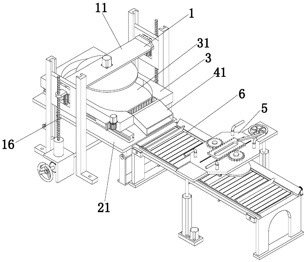
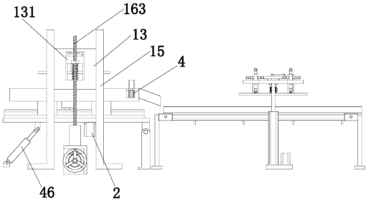
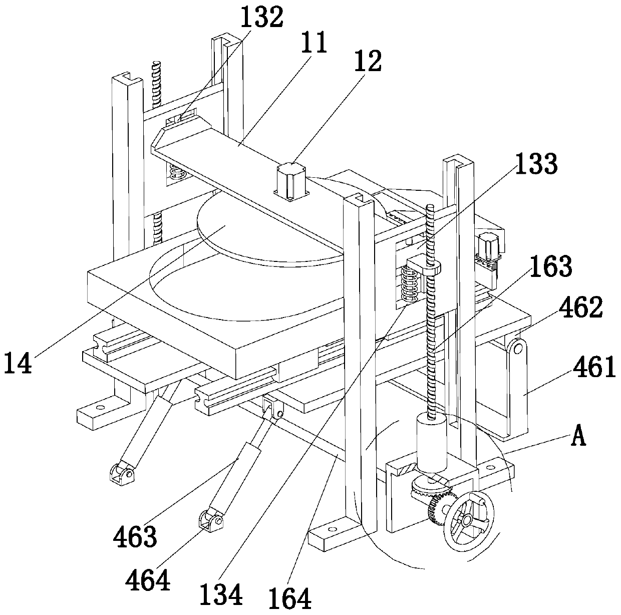
[0031] The present invention provides an integrated machine for polishing and cleaning the surface of steel balls through improvements, such as Figure 1-Figure 7 As shown, it includes a steel ball automatic grinding mechanism 1, a reciprocating material moving and turning mechanism 2, a bearing platform 3, an automatic discharging mechanism 4, a steel ball scrubbing mechanism 5, and a horizontally arranged plate chain conveyor belt 6, which is automatically polished The mechanism 1 is arranged above the carrying platform 3, the plate chain conveyor 6 is arranged on the right side of the carrying platform 3, the steel ball scrubbing mechanism 5 is arranged above the plate chain conveyor 6, and the reciprocating material is turned over The mechanism 2 is arranged below the carrying platform 3. The automatic unloading mechanism 4 is used to make the carrying platform 3 inclined. The top of the carrying platform 3 is provided with an elliptical groove 31, and the side wall of the elliptical groove 31 is provided There is a flexible buffer layer, the bottom of the elliptical groove 31 is provided with a grinding layer, the reciprocating material moving and turning mechanism 2 includes a supporting plate 21, a driving material moving assembly 7 and two sliding plates horizontally arranged on the top of the supporting plate 21 Each of the slide rails 22 is provided with a support block 23 that is slidably matched with the support block 23. The bearing platform 3 is installed on top of the two support blocks 23; under the action of the steel ball automatic grinding mechanism 1, the steel ball The top surface of the ball is polished. The steel ball in the elliptical groove 31 can be polished under the cooperation of the grinding layer and the grinding wheel 14, and the steel ball can be rolled under the work of the reciprocating material shifting and turning mechanism 2 to facilitate the The other surface of the steel ball is polished. The advantage of providing the elliptical groove 31 is that it facilitates the turning of the steel ball. The two sides of the elliptical groove 31 have a semicircular structure to facilitate the grinding wheel 14 to polish the steel ball.
[0032] Specifically, the driving material-moving assembly 7 includes a driving motor 71, a rotating shaft 72 vertically arranged on the top of the supporting plate 21, and an extension frame 73 arranged on the bottom of the carrying platform 3, and the rotating shaft 72 rotates with the supporting plate 21. The drive motor 71 is arranged at the bottom of the support plate 21, and the output shaft of the drive motor 71 is coaxially connected with the bottom end of the rotating shaft 72, the extension frame 73 is provided with a strip groove 74, and the rotating shaft 72 is sleeved with a connecting bar 75, and the end of the connecting bar 75 is provided with a drive head 76 slidingly fitted with the bar groove 74; the drive motor 71 can drive the rotating shaft 72 to rotate, so that the rotating shaft 72 can drive the connection The strip 75 rotates so that the connecting strip 75 can drive the driving head 76 to rotate, so that the driving head 76 can be slidably engaged with the strip groove 74, and then the extension frame 73 is moved, so that the bearing platform 3 is along the length direction of the slide rail 22 The reciprocating movement is performed to make the steel ball located in the elliptical groove 31 roll back and forth for turning over, which is convenient for the grinding wheel 14 to fully grind the steel ball.
[0033] Specifically, the steel ball automatic grinding mechanism 1 includes a lifting seat 11, a height adjustment assembly 16, a grinding motor 12 arranged on the top of the lifting seat 11, and two vertical lifting plates 13, the grinding motor 12 The output end faces vertically downwards, and the output end of the polishing motor 12 is sleeved with a polishing wheel 14. Both sides of the lifting vertical plate 13 are provided with a supporting rail 15, the lifting vertical plate 13 and two supporting rails 15 Sliding fit, the lifting vertical plate 13 is provided with a sliding groove 131, a vertically arranged sliding rod 132 is provided in the sliding groove 131, and a sliding block 133 is sleeved on the sliding rod 132 to be slidingly matched with it. A buffer spring 134 is sleeved on the sliding rod 132, two ends of the buffer spring 134 are respectively connected to the bottom end of the sliding block 133 and the bottom of the sliding groove 131, and the lifting seat 11 is fixed to the two sliding blocks 133. Between; under the action of the steel ball automatic grinding mechanism 1, the top surface of the steel ball is automatically polished, so that the steel ball can polish the steel ball in the elliptical groove 31 under the cooperation of the grinding layer and the grinding wheel 14. The reciprocating material-moving and turning-over mechanism 2 can roll the steel ball to facilitate the grinding of other surfaces of the steel ball. The grinding wheel 14 can drive the steel ball to roll during the rotation, and the reciprocating material-moving-turning mechanism 2 The steel ball can be turned over in the horizontal direction to automatically grind the steel ball. The support rail 15 is used to guide the lifting vertical plate 13, the sliding rod 132 is used to guide the sliding block 133, and the sliding block 133 is moving. During the process, the lifting seat 11 can be driven to move vertically, and the buffer spring 134 can buffer the lifting seat 11, thereby reducing the impact force of the grinding wheel 14 on the steel ball.
[0034] Specifically, the height adjustment assembly 16 includes two mounting seats 161 arranged at intervals and two bearing seats 162 respectively arranged on the tops of the two mounting seats 161, and each of the bearing seats 162 is provided with a rotational connection therewith. The transmission screw 163, each transmission screw 163 corresponds to a lifting vertical plate 13, and the lifting vertical plate 13 is provided with a threaded sleeve that is threaded with the corresponding transmission screw 163. Between the seats 161 is provided a transmission shaft 164 which is rotatably connected to the two. Both ends of the transmission shaft 164 are sleeved with first bevel gears 165, and the bottom ends of the two transmission screw rods 163 are sleeved with Two bevel gears 166, the two first bevel gears 165 mesh with two second bevel gears 166, and the end of the transmission shaft 164 is sleeved with a hand wheel 167; the worker can make the transmission through the hand wheel 167 The shaft 164 rotates, so that the transmission shaft 164 can drive the first bevel gear 165 to rotate, and the first bevel gear 165 can drive the second bevel gear 166 meshed with it to rotate, so that the two transmission screw rods 163 can rotate simultaneously. The drive screw 163 can drive the lifting vertical plate 13 to move vertically, so that the lifting seat 11 drives the grinding wheel 14 to grind the steel ball at a certain height. The manual driving method is used to adjust the height of the grinding wheel 14 with high precision in real time. .
[0035] Specifically, the automatic unloading mechanism 4 includes an angle adjustment assembly 46 and a discharge nozzle 41 arranged on the right side of the carrying platform 3, and the discharge nozzle 41 communicates with the inside of the elliptical groove 31, and the right side of the carrying platform 3 The side is provided with a sliding plate 42 which is slidingly matched with it. The top of the carrying table 3 is provided with a stepping motor 43, the output end of the stepping motor 43 is arranged downward, and the output end of the stepping motor 43 is sleeved Transmission gear 44, the left side of the sliding plate 42 is provided with a rubber buffer layer, and the right side of the sliding plate 42 is provided with a tooth groove 45 meshing with the transmission gear 44; when the unloading of the steel ball is to be completed, The stepping motor 43 works to drive the transmission gear 44 to rotate, so that the transmission gear 44 can drive the sliding plate 42 meshing with it to move horizontally, so that the sliding plate 42 can open the discharge port of the discharge nozzle 41. At this time, two The cylinder 463 is driven to work at the same time to make the support plate 21 incline, so that the steel balls can be discharged to the plate chain conveyor 6 through the discharge nozzle 41, so that the steel balls can be cleaned. The rubber buffer layer can avoid steel The ball contacts the sliding plate 42 and damages the steel ball.
[0036] Specifically, the angle adjustment assembly 46 includes a mounting frame 461, a connecting plate 462 provided at the bottom left side of the support plate 21, two driving cylinders 463 and two cylinder seats 464 arranged at intervals. The connecting plate 462 and the mounting The frame 461 is hinged, the tails of the two driving cylinders 463 are hinged to the two cylinder seats 464, and the output ends of the two driving cylinders 463 are hinged to the bottom of the support plate 21; the two driving cylinders 463 work simultaneously, The supporting plate 21 is inclined so that the steel balls can be discharged onto the plate chain conveyor 6 through the discharge nozzle 41.
[0037] Specifically, the steel ball scrubbing mechanism 5 includes a mounting table 51, two scrubbing wheels 52, and two connecting shafts 53 spaced apart on the top of the mounting table 51. The two scrubbing wheels 52 are respectively sleeved on two connecting shafts. At the bottom end of the shaft 53, the two connecting shafts 53 are connected with the mounting table 51 through bearings. The bottoms of both sides of the mounting table 51 are provided with vertically arranged lifting electric cylinders 54. The mounting table 51 Two infusion pipes 55 are provided for each scrubbing wheel 52, and an atomizing nozzle 551 is provided on the infusion end of each infusion pipe 55; the steel ball scrubbing mechanism 5 can make the two scrubbing wheels 52 relatively rotate. Brush the steel ball to make the surface of the steel ball clean thoroughly. Under the action of the lifting electric cylinder 54, the mounting table 51 can be moved up and down to adjust the height position of the two scrubbing wheels 52 with high precision. The cleaning liquid is conveyed in the liquid infusion pipe 55, so that the atomizing nozzle 551 can spray the cleaning liquid to the steel ball in an atomized state to complete the cleaning of the steel ball.
[0038] Specifically, the steel ball scrubbing mechanism 5 further includes a rotating motor 56 and two rotating gears 561 respectively sleeved on the top ends of the two connecting shafts 53. The top of the mounting table 51 is provided with a reciprocating material slidingly engaged with it. The two sides of the reciprocating material plate 562 are respectively provided with tooth surfaces 563 meshing with two rotating gears 561. The rotating electric machine 56 is arranged on the bottom of the mounting table 51, and the output end of the rotating electric machine 56 is A transmission wheel 57 is sleeved. The transmission wheel 57 is provided with an articulated transmission rod 58 which is hinged to the reciprocating material plate 562; the rotation motor 56 can drive the transmission wheel 57 to rotate and make the transmission wheel 57 can drive the reciprocating material plate 562 through the transmission rod 58 to move, so that the reciprocating material plate 562 can drive the two rotating gears 561 meshed with it to rotate, one rotating gear 561 rotates clockwise, and the other rotating gear 561 counterclockwise The hour hand rotates to clean the surface of the steel ball.
[0039] Specifically, the top of the plate chain conveyor belt 6 is provided with a plurality of partition plates 61 arranged at equal intervals along the conveying direction, and the several partition plates 61 divide the plate chain conveyor belt 6 into a plurality of cleaning areas 62 , Both sides of the plate chain conveyor belt 6 are provided with baffle plates 63, the partition plate 61 is made of flexible material; the partition plate 61 can divide the plate chain conveyor belt 6 into a plurality of cleaning areas 62, Each cleaning area 62 can store different batches of steel balls to avoid mixing steel balls of different specifications and causing trouble for workers' screening. The baffle plate 63 can prevent the steel balls from falling; 61 is made of a flexible material to prevent the steel ball from contacting the partition plate 61 and damage the steel ball.
[0040] The working principle of the present invention: the worker manually places the steel ball in the elliptical groove 31, under the action of the steel ball automatic grinding mechanism 1, the top surface of the steel ball is automatically polished, and under the cooperation of the grinding layer and the grinding wheel 14 The steel ball in the elliptical groove 31 can be polished, and the steel ball can be rolled under the work of the reciprocating material shifting and turning mechanism 2, so as to polish other surfaces of the steel ball. The grinding wheel 14 can be driven during the rotation The steel ball rolls, and the reciprocating material-moving turning mechanism 2 can turn the steel ball in the horizontal direction to automatically polish the steel ball. Specifically, the worker can make the drive shaft 164 happen through the handwheel 167. Rotation enables the transmission shaft 164 to drive the first bevel gear 165 to rotate, so that the first bevel gear 165 can drive the second bevel gear 166 meshed with it to rotate, thereby causing the two drive screw rods 163 to rotate at the same time, so that the transmission wire The rod 163 can drive the lifting vertical plate 13 to move vertically, so that the lifting seat 11 drives the grinding wheel 14 to polish the steel ball at a certain height. The drive motor 71 can drive the rotating shaft 72 to rotate, so that the rotating shaft 72 can drive The connecting bar 75 rotates, so that the connecting bar 75 can drive the driving head 76 to rotate, so that the driving head 76 can be slidably matched with the strip groove 74, and then the extension frame 73 is moved, so that the bearing platform 3 is along the length of the slide rail 22 Move back and forth in the direction to make the steel ball located in the elliptical groove 31 roll back and forth for turning over, which is convenient for the grinding wheel 14 to fully polish the steel ball;
[0041] After the polishing is completed, the stepping motor 43 works to drive the transmission gear 44 to rotate, so that the transmission gear 44 can drive the sliding plate 42 meshed with it to move horizontally, so that the sliding plate 42 can open the discharge port of the discharge nozzle 41. At this time, the two driving cylinders 463 work at the same time to make the support plate 21 inclined, so that the steel balls can be discharged to the plate chain conveyor 6 through the discharge nozzle 41, so as to facilitate the cleaning of the steel balls;
[0042] The steel ball scrubbing mechanism 5 can make the two scrubbing wheels 52 relatively rotate to scrub the steel balls, so that the surface of the steel balls can be cleaned thoroughly, and the mounting table 51 can be moved up and down under the action of the lifting electric cylinder 54. The height position of the two scrubbing wheels 52 is adjusted with high precision. The worker delivers the cleaning liquid into the liquid infusion pipeline 55, so that the atomizing nozzle 551 can spray the cleaning liquid to the steel ball in an atomized state to complete the cleaning of the steel ball. At the same time, the rotating motor 56 can drive the transmission wheel 57 to rotate, so that the transmission wheel 57 can drive the reciprocating material plate 562 through the transmission rod 58 to move, so that the reciprocating material plate 562 can drive the two meshing rotations. The gear 561 rotates, one rotating gear 561 rotates clockwise, and the other rotating gear 561 rotates counterclockwise to clean the surface of the steel ball.
[0043] The foregoing description of the disclosed embodiments enables those skilled in the art to implement or use the present invention. Various modifications to these embodiments will be obvious to those skilled in the art, and the general principles defined in this document can be implemented in other embodiments without departing from the spirit or scope of the present invention. Therefore, the present invention will not be limited to the embodiments shown in this document, but should conform to the widest scope consistent with the principles and novel features disclosed in this document.

PUM

no PUM

Description & Claims & Application Information

We can also present the details of the Description, Claims and Application information to help users get a comprehensive understanding of the technical details of the patent, such as background art, summary of invention, brief description of drawings, description of embodiments, and other original content. On the other hand, users can also determine the specific scope of protection of the technology through the list of claims; as well as understand the changes in the life cycle of the technology with the presentation of the patent timeline. Login to view more.
Why Eureka
Try Eureka