A plastic mold with vibration function

A plastic mold and function technology, applied in the field of plastic molds with vibration function, can solve the problems of molten plastic casting failure, high subjectivity, low efficiency and so on.

Active Publication Date: 2019-04-02
กวางตุ้ง คิวแมน คัลเจอร์ คอมมูนิเคชั่น โค แอลทีดี
View PDF2 Cites 0 Cited by
  • Summary
  • Abstract
  • Description
  • Claims
  • Application Information

AI Technical Summary

Problems solved by technology

[0006] In order to overcome the existence of the surface tension of the molten plastic in the prior art, the present invention often occurs that some parts of the raw material “cut off” and the mold cannot be filled with the molten plastic, resulting in casting failure, low efficiency, high subjectivity, and low labor efficiency. , the shortcoming that the output cannot be predicted and guaranteed, the technical problem to be solved by the present invention is to provide a method that can ensure that the raw material will not be cut off, so that the concave mold is filled with molten plastic, and the labor efficiency and production efficiency can be improved. At the same time, the output and production efficiency can be predicted Plastic mold with vibration function for guaranteed output

Method used


Image

  • A plastic mold with vibration function
  • A plastic mold with vibration function
  • A plastic mold with vibration function

Examples


Embodiment 1

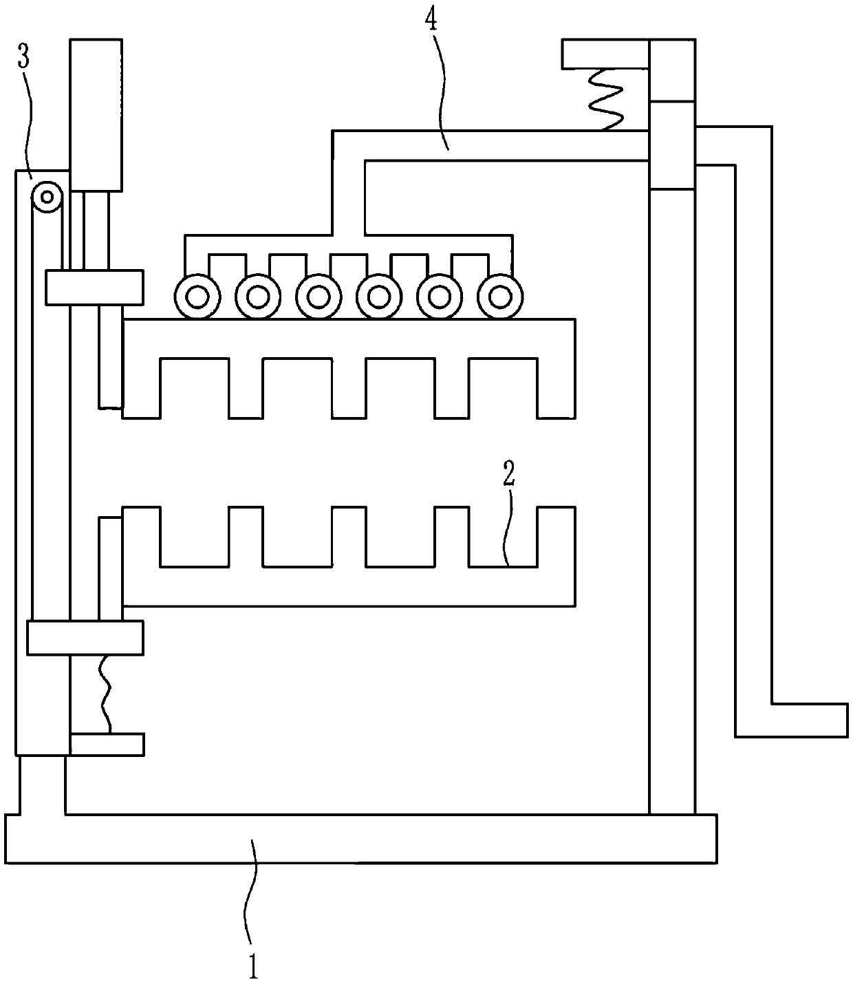
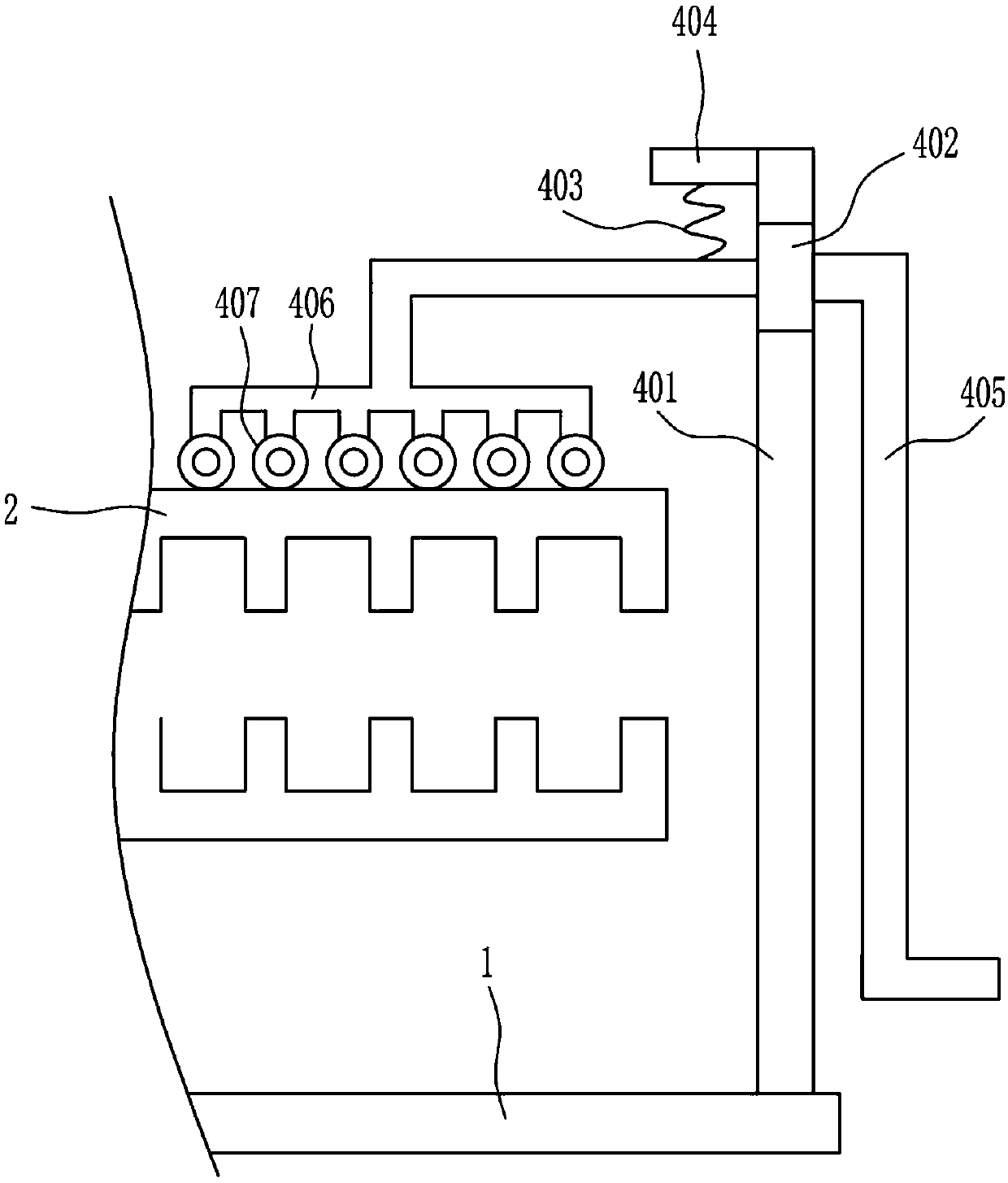
[0036] A plastic mold with vibration function, such as Figure 1-7 As shown, it includes bottom plate 1, mold cavity 2, closing mechanism 3 and lifting mechanism 4. The left top of bottom plate 1 is connected with closing mechanism 3, and the right end of closing mechanism 3 is connected with mold cavity 2 up and down. The top right side of bottom plate 1 A lifting mechanism 4 is connected, and the bottom of the lifting mechanism 4 is in contact with the top of the upper mold cavity 2 .

Embodiment 2

[0038] A plastic mold with vibration function, such as Figure 1-7 As shown, it includes bottom plate 1, mold cavity 2, closing mechanism 3 and lifting mechanism 4. The left top of bottom plate 1 is connected with closing mechanism 3, and the right end of closing mechanism 3 is connected with mold cavity 2 up and down. The top right side of bottom plate 1 A lifting mechanism 4 is connected, and the bottom of the lifting mechanism 4 is in contact with the top of the upper mold cavity 2 .

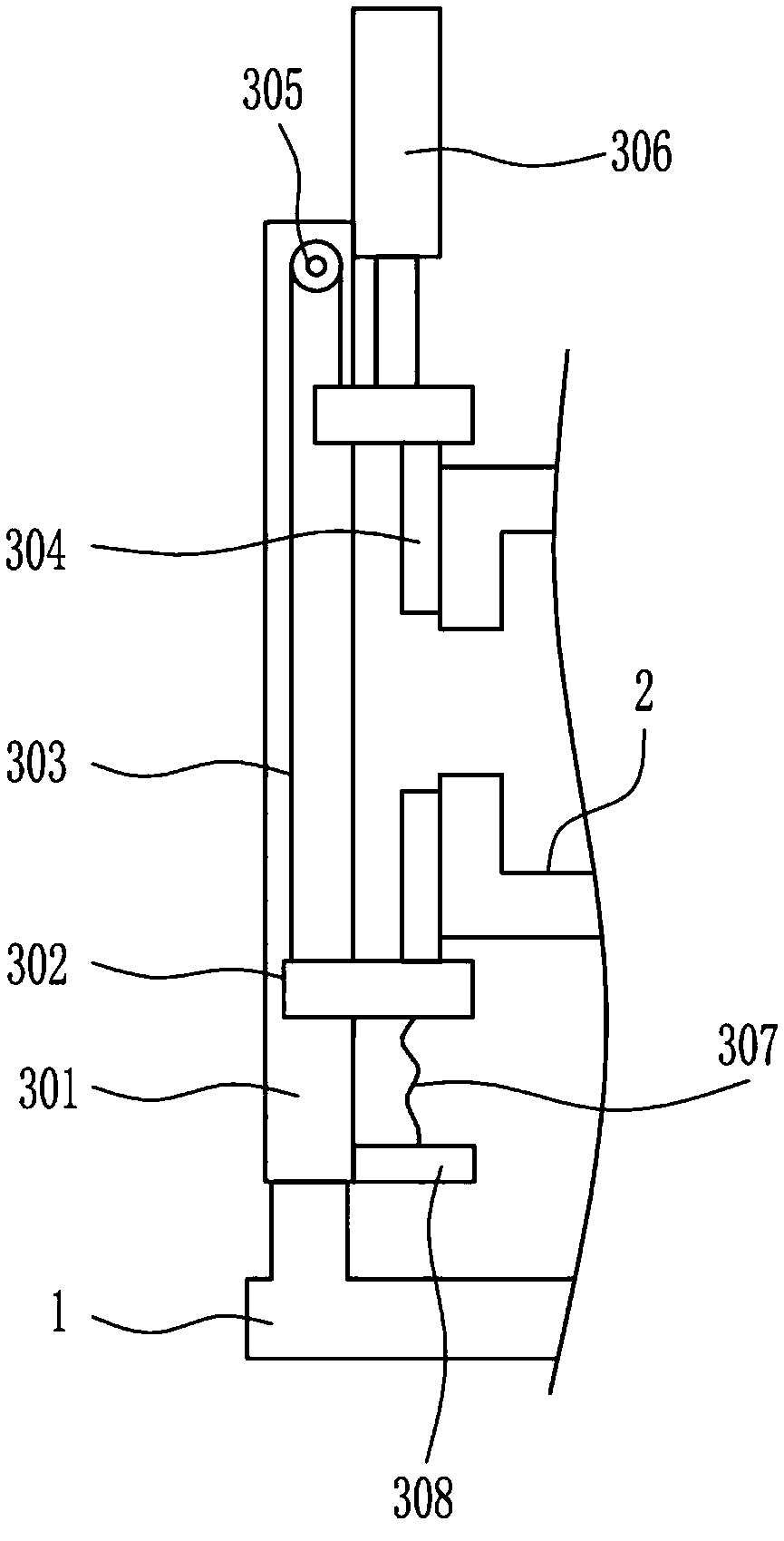
[0039] The closing mechanism 3 includes a first slide rail 301, a first slider 302, a first wire rope 303, a first connecting rod 304, a guide wheel 305, an electric push rod 306, a first spring 307 and a first pole 308, and the base plate 1 The first slide rail 301 is connected to the top left side of the first slide rail 301, and the first slide block 302 is slidably connected to the upper and lower sides of the first slide rail 301. The first slide block 302 cooperates with the first slide...

Embodiment 3

[0041] A plastic mold with vibration function, such as Figure 1-7 As shown, it includes bottom plate 1, mold cavity 2, closing mechanism 3 and lifting mechanism 4. The left top of bottom plate 1 is connected with closing mechanism 3, and the right end of closing mechanism 3 is connected with mold cavity 2 up and down. The top right side of bottom plate 1 A lifting mechanism 4 is connected, and the bottom of the lifting mechanism 4 is in contact with the top of the upper mold cavity 2 .

[0042] The closing mechanism 3 includes a first slide rail 301, a first slider 302, a first wire rope 303, a first connecting rod 304, a guide wheel 305, an electric push rod 306, a first spring 307 and a first pole 308, and the base plate 1 The first slide rail 301 is connected to the top left side of the first slide rail 301, and the first slide block 302 is slidably connected to the upper and lower sides of the first slide rail 301. The first slide block 302 cooperates with the first slide...


PUM


Abstract

The invention relates to a plastic mold, in particular to a plastic mold with a vibration function. According to the plastic mold with the vibration function, the result that raw materials are not cut off can be ensured, so that female molds are filled with molten plastic; the labor efficiency and the production efficiency are improved; and meanwhile, the yield also can be predicted and ensured. The plastic mold with the vibration function comprises a bottom plate and the like. A closing mechanism is connected to the top of the left side of the bottom plate. Mold cavities are connected to the right end of the closing mechanism up and down. A lifting mechanism is connected to the right side of the top of the bottom plate. The bottom of the lifting mechanism makes contact with the tops of the upper-side mold cavities. By means of the plastic mold with the vibration function, the effects that the result that the raw materials are not cut off can be ensured, so that the female molds are filled with the molten plastic; the labor efficiency and the production efficiency are improved; and meanwhile, the yield also can be predicted and ensured are achieved.

Description

technical field [0001] The invention relates to a plastic mold, in particular to a plastic mold with vibration function. Background technique [0002] Plastic molds are tools that are matched with plastic molding machines in the plastic processing industry to give plastic products a complete configuration and precise dimensions. Due to the variety of plastics and processing methods, and the structures of plastic molding machines and plastic products, the types and structures of plastic molds are also varied. It mainly consists of parts such as die combination substrate, die assembly and die combination. There is a molding cavity in this combination. During injection molding, the mold is clamped on the injection molding machine, the molten plastic is injected into the molding cavity, and cooled and shaped in the cavity, then the upper and lower molds are separated, and the product is ejected from the cavity through the ejector system to leave the mold, and finally the mold i...

Claims


Application Information

Patent Timeline
Patent Type & Authority Patents(China)
IPC IPC(8): B29C45/56B29C45/66
CPCB29C45/568B29C45/66B29C2045/5685
Inventor 金吉祥曾庆忠谢真
Owner กวางตุ้ง คิวแมน คัลเจอร์ คอมมูนิเคชั่น โค แอลทีดี
Why Eureka
Try Eureka