
Design method for rubber profile of traction rod node and traction rod node

A technology of traction tie rod and design method, which is applied in railway car body parts, bogies, transportation and packaging, etc., can solve the problems of cracks or wrinkles, wrinkle cracking, and short fatigue life on the profile surface, so as to reduce wrinkles and cracks, The effect of reducing rubber bulge and improving deformation characteristics

Active Publication Date: 2017-11-21
ZHUZHOU TIMES NEW MATERIALS TECH
View PDF9 Cites 14 Cited by
  • Summary
  • Abstract
  • Description
  • Claims
  • Application Information

AI Technical Summary

Problems solved by technology

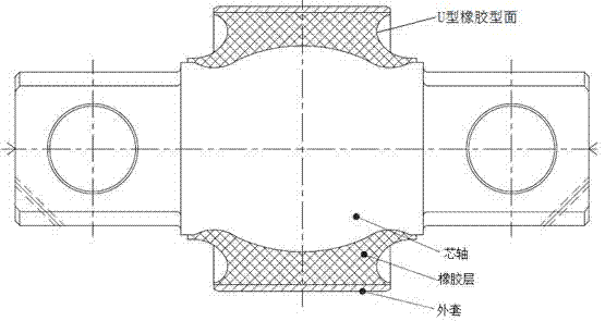
[0004] 1. The U-shaped rubber surface will be disassembled during the load-bearing process, and cracks or wrinkles will be formed on the surface
[0005] 2. During the bearing process, the rubber body bulges from the middle of the rubber profile to the upper and lower ends, and the reciprocating deformation of the rubber layer is prone to wrinkle cracking and extrusion cracking near the jacket and the mandrel
[0006] 3. The stiffness of the nodes changes under heavy loads, which cannot meet the stiffness requirements under heavy loads
[0007] 4. The initial stiffness and initial stress of the nodes cannot be adjusted according to the bearing requirements of different lines
[0008] The above defects cause the traction rod nodes in the prior art to have short fatigue life under heavy load conditions, and the stiffness changes during the loading process are small, which cannot meet the nonlinear stiffness requirements under heavy loads

Method used


Image

  • Design method for rubber profile of traction rod node and traction rod node
  • Design method for rubber profile of traction rod node and traction rod node
  • Design method for rubber profile of traction rod node and traction rod node

Examples


Embodiment Construction

[0031] Attached below Figures 2 to 4 Embodiments of the present invention are described in detail.

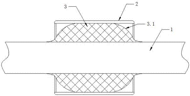
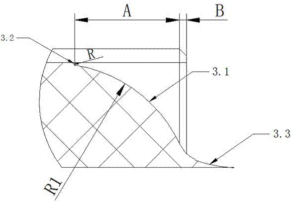
[0032] The rubber profile design method of the traction rod node, including the mandrel 1, the outer shell 2 and the rubber layer 3 vulcanized and bonded between the mandrel 1 and the outer shell 2, is characterized in that the outer end profile of the rubber layer 3 is designed to The circular arc convex surface 3.1 protruding outward, the circular arc convex surface 3.1 gradually approaches the inner wall of the jacket 2 from the outside to the inside, and the arc convex surface 3.1 and the inner wall of the jacket 2 are transitioned through the transition surface 3.2, and the circular arc convex surface 3.1 and the core The outer walls of the shaft 1 are transitioned through the transition surface 2 3.3, the transition surface 3.2 is designed as an inwardly concave arc surface, and the transition surface 2 3.3 is designed as an inwardly concave arc surface.

[0033] Such a...


PUM


Abstract

Disclosed is a design method for a rubber profile of a traction rod node. A mandrel, a jacket and a rubber layer vulcanized and adhered between the mandrel and the jacket are included. The method is characterized in that the outer end profile of the rubber layer is designed as an outwardly projecting arc convex surface, the arc convex surface gets gradually close to the inner wall of the jacket from outside to inside, the arc convex surface and the inner wall of the jacket are transitioned through a first transition surface, the arc convex surface and the outer wall of the mandrel are transitioned through a second transition surface, the first transition surface is designed as an inwardly recessed arc surface, and the second transitional surface is designed as an inwardly recessed cambered surface. By applying the design method for the rubber profile of the traction rod node, wrinkles and cracks of the rubber profile during the bearing process are decreased, the fatigue life of the traction rod node under large load is improved, and the nonlinear stiffness of the traction rod node under large load is met. The invention also provides the traction rod node.

Description

technical field [0001] The invention relates to a rubber profile design method for a traction rod node, which is used to improve the fatigue life of the traction rod node under heavy load, and also relates to a traction rod node. Background technique [0002] The traction rod node is an important part of class B, installed at both ends of the bogie draw rod, one end is connected with the car body, and the other end is fixed to the bogie, which mainly plays the role of transmitting traction, but when the bogie is passing the curve, the traction rod Nodes need to provide elastic effects such as torsional deformation and deflection deformation. The traction link nodes work together with air springs and other rubber components to provide stable and comfortable running performance for the car body. Its main function is to transmit traction and braking force. If the product stiffness is too high, it will affect the shock absorption and buffering effect and affect the comfort of...

Claims


Application Information

Patent Timeline
IPC IPC(8): B61F5/50
CPCB61F5/50
Inventor 雷军玉荣继刚张玉祥蒋仲三曾先会曾慧
Owner ZHUZHOU TIMES NEW MATERIALS TECH
Learn More