
Roving frame

A technology of roving frames and racks, applied in the field of textile processing, which can solve problems such as fiber dispersion, uniform guidance of rovings, and single structure, and achieve the effects of avoiding temperature rise, increasing friction, and not easy to slip

Pending Publication Date: 2017-11-21
ZHEJIANG YILEI WOOLLEN SPINNING & WEAVING
View PDF6 Cites 1 Cited by
  • Summary
  • Abstract
  • Description
  • Claims
  • Application Information

AI Technical Summary

Problems solved by technology

But the existing roving frame has the disadvantages of the following aspects: 1. When the existing yarn-drawing mechanism draws the fibers, the fibers are relatively scattered and the degree of gathering is revealed;
2. The structure of the rubbing mechanism on the existing roving frame is single, and the rubbing effect of the rubbing mechanism is not good, mainly because the rubbing force of the rubbing mechanism for the fibers is insufficient, and the degree of twisting of the obtained roving is relatively low and relatively loose.
3. After the rubbing mechanism twists the fibers into rovings, the yarn guiding mechanism needs to guide the rovings to the receiving bobbin, but the existing yarn guiding mechanism cannot evenly guide the rovings to the bobbin, which is very easy to cause The case where the partial winding of the cylinder is bloated
4. Broken fibers (such as short piles and hair balls) in the raw material fibers will affect the forming effect of the roving, so it is difficult for the twisting mechanism to twist it into a relatively tight roving, which is in urgent need of improvement

Method used


Image

  • Roving frame
  • Roving frame
  • Roving frame

Examples


Embodiment Construction

[0021] The preferred embodiments of the present invention will be described in further detail below in conjunction with the accompanying drawings.

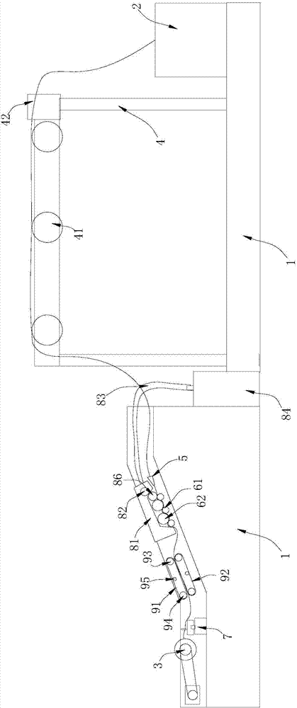
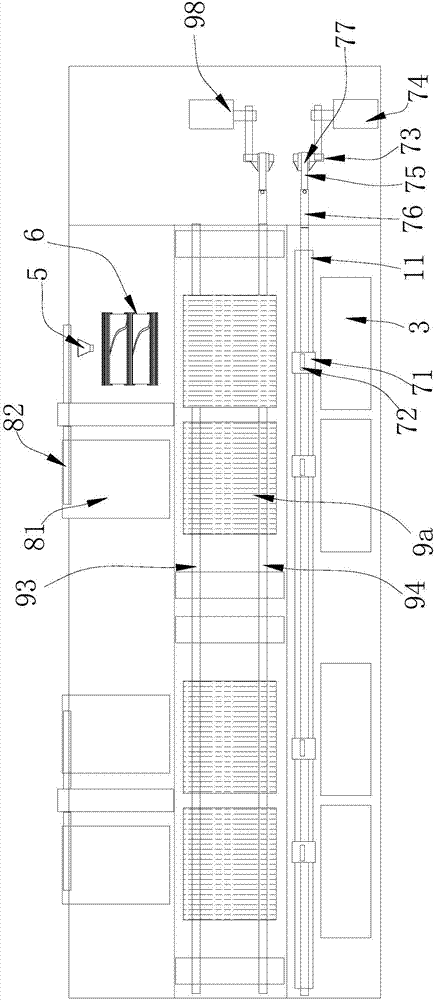
[0022] Such as Figure 1~4 A roving frame shown includes a frame 1, a discharge barrel 2 and a winding spindle 3 arranged on the frame 1, and a rubbing mechanism and yarn drawing arranged between the discharge barrel 2 and the winding spindle 3 mechanism.

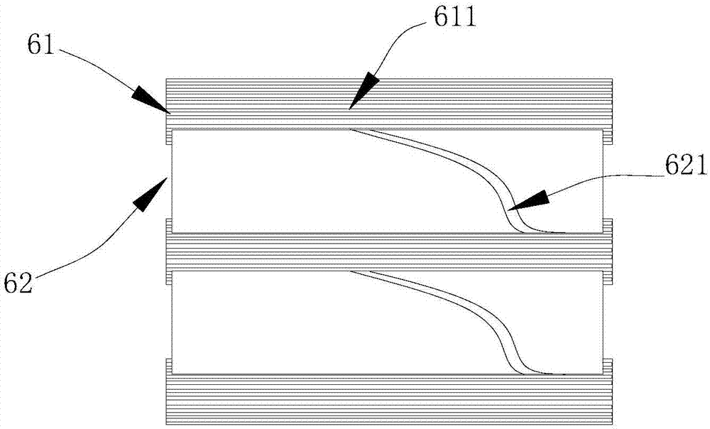
[0023] The yarn guiding mechanism includes a fiber guide frame 4 between the yarn rubbing mechanism and the discharge barrel 2, a limit sleeve 5 and a fiber traction assembly 6, and a yarn guiding assembly 7 between the yarn rubbing mechanism and the yarn receiving spindle 3 . The fiber guide frame 4 is above the fiber traction assembly 6, the fiber guide frame 4 is provided with a guide roller shaft 41, and several partition plates 42 arranged along the axial gap of the guide roller shaft 41, between two adjacent partition plates 42 Each fiber guide groove is used to guide ...


PUM


Abstract

The invention relates to the field of textile processing, and in particular to a roving frame. The roving frame comprises a rack, a discharging barrel, a yarn collecting spindle, a yarn twisting mechanism and a yarn drawing mechanism, wherein the discharging barrel and the yarn collecting spindle are arranged on the rack; the yarn twisting mechanism and the yarn drawing mechanism are arranged between the discharging barrel and the yarn collecting spindle; the yarn drawing mechanism comprises a fiber guiding frame, a limiting and closing sleeve and a fiber drawing assembly, which are located between the yarn twisting mechanism and the discharging barrel, and a yarn guiding assembly, which is located between the yarn twisting mechanism and the yarn collecting spindle. Roving obtained through the roving frame disclosed by the invention is tighter.

Description

technical field [0001] The invention relates to the field of textile processing, in particular to a roving frame. Background technique [0002] A roving frame is a spinning machine that turns sliver into roving. The roving frame mainly includes a yarn drawing mechanism to draw the fibers, and twist the fibers into rovings through the yarn rubbing mechanism. But existing roving frame has the weak point of the following aspects: 1, when existing yarn drawing mechanism pulls fiber, fiber is comparatively scattered, and gathering degree is revealed; 2. The structure of the rubbing mechanism on the existing roving frame is single, and the rubbing effect of the rubbing mechanism is not good, mainly because the rubbing force of the rubbing mechanism for the fibers is insufficient, and the degree of twisting of the obtained roving is relatively low and relatively loose. 3. After the rubbing mechanism twists the fibers into rovings, the yarn guiding mechanism needs to guide the rov...

Claims


Application Information

Patent Timeline
Patent Type & Authority Applications(China)
IPC IPC(8): D01H1/00D01H13/04D01H7/02D01H1/16D01H11/00
CPCD01H1/00D01H1/16D01H7/02D01H11/00D01H13/04
Inventor 沈国良
Owner ZHEJIANG YILEI WOOLLEN SPINNING & WEAVING
Learn More