Wear indicator for adjusting arm and brake clearance adjusting arm

A wear indicator and brake clearance technology, which is applied in the mechanical field, can solve the problems of narrow space, relatively high requirements, scattered distribution of brake lining alarm devices, etc., and achieve the effect of improving matching accuracy and ensuring rotation stability

Pending Publication Date: 2017-11-21
LONGZHONG HLDG GRP
View PDF8 Cites 7 Cited by
  • Summary
  • Abstract
  • Description
  • Claims
  • Application Information

AI Technical Summary

Problems solved by technology

[0004] Although the above-mentioned automatic brake clearance adjuster for automobiles can give an alarm in time when the brake lining wears to the limit through the setting of the brake lining wear alarm device, it also has some shortcomings: after being installed on the car, adjust The housing of the brake is connected with the brake air chamber, and the shift fork is fixed on the automobile axle to keep it still, while the space between the brake air chamber and the automobile axle position is relatively narrow, which is used to realize the braking of the brake lining. The wear alarm lever is fixed on one of the dial rings and is directly exposed outside, and the micro switch is fixed on the housing and is directly exposed outside. On the one hand, the distribution of the e

Method used


Image

  • Wear indicator for adjusting arm and brake clearance adjusting arm
  • Wear indicator for adjusting arm and brake clearance adjusting arm
  • Wear indicator for adjusting arm and brake clearance adjusting arm

Examples


Example Embodiment

[0045] The following are specific embodiments of the present invention in conjunction with the accompanying drawings to further describe the technical solutions of the present invention, but the present invention is not limited to these embodiments.
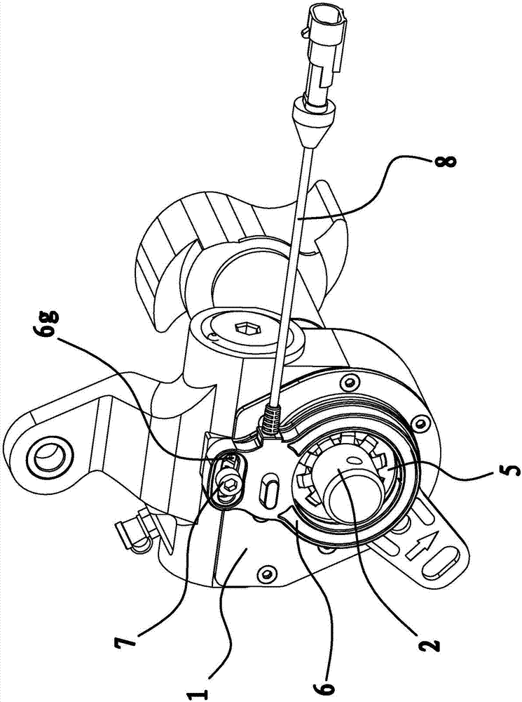
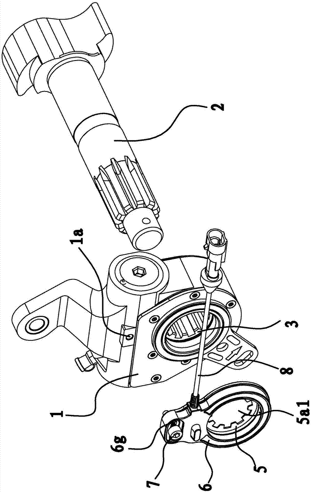
[0046] Such as figure 1 with figure 2 As shown, a brake gap adjustment arm includes a housing 1, a worm gear 3, and a camshaft 2. The worm gear 3 is arranged in the housing 1 and can rotate relative to the housing 1, and one end of the camshaft 2 is inserted into the housing 1. , The worm gear 3 is sleeved on the camshaft 2 and matched with the camshaft 2 through splines. The specific structure of the automobile brake clearance adjustment arm can refer to the automatic adjustment of the automobile brake clearance with the application number 201611140721.8 previously filed by the applicant. arm.

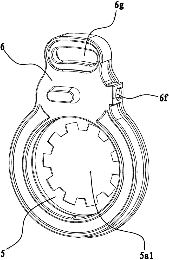
[0047] The wear indicator includes a rotating disk 5, an on-off switch 4, and a mounting box 6. The mounting box 6 is connected to one side...


PUM


Abstract

The invention provides a wear indicator for an adjusting arm and a brake clearance adjusting arm and belongs to the technical field of machinery. The problems that the conventional wear indicator is easily interfered and accurate alarm cannot be ensured are solved. The wear indicator for the adjusting arm comprises an on-off type switch, a mounting box and a rotating disc, wherein the on-off type switch is arranged in the mounting box; the mounting box comprises a limiting hole; the rotating disc is positioned in the limiting hole, and radial limiting is formed between the rotating disc and the limiting hole; circular grooves are formed in inner walls of the limiting hole; the outer edge of the rotating disc is positioned in the circular grooves, and the rotating disc is limited between groove walls on two sides of the circular grooves; the circular grooves are partially or completely penetrated, and the rotating disc can rotate relative to the mounting box; a protrusion part capable of triggering the on-off type switch is arranged on a part, which penetrates through the circular groove, of the rotating disc. The wear indicator for the adjusting arm and the brake clearance adjusting arm disclosed by the invention have the advantages of high working accuracy, difficulty in interference and the like.

Description

technical field [0001] The invention belongs to the technical field of machinery, and relates to a wear indicator for an adjusting arm and a brake clearance adjusting arm. Background technique [0002] The normal braking of the car is achieved through the contact between the brake drum and the brake shoe friction lining in the drum brake and the use of friction. The car brake clearance refers to the gap between the brake drum and the brake shoe friction lining. The gap that must be maintained, the friction lining will wear out during the long-term friction and the brake gap will become larger and larger, so a brake that can automatically adjust the brake shoe and the brake drum must be installed in the brake mechanism. The adjustment arm of the gap, such as the Chinese patent once disclosed a car brake gap automatic adjuster [application number: 03227352.5] with a brake lining wear alarm device, which includes a camshaft installed on the S-shaped brake shaft of the car, The...

Claims


Application Information

Patent Timeline
IPC IPC(8): F16D66/02F16D65/52
CPCF16D65/52F16D66/025
Inventor 苏辉胡志勇杨来科罗少卿肖水波王帮华
Owner LONGZHONG HLDG GRP
Why Eureka
Try Eureka