
Tool holder of machine tool

A tool holder and machine tool technology, applied in the field of tool holders, can solve the problem of difficult flow of cutting fluid, and achieve the effect of ensuring rotational stability

Inactive Publication Date: 2005-09-14
HORKOS
View PDF0 Cites 1 Cited by
  • Summary
  • Abstract
  • Description
  • Claims
  • Application Information

AI Technical Summary

Problems solved by technology

[0008] In this situation, when the tool holder reaches about 6,000 revolutions per minute or more, the stagnant mist cutting fluid supplied to the mist cutting fluid passages 9c, 8f or the closed space 12 will receive the centrifugal force generated by the rotation. To promote its liquefaction, since the liquefied cutting fluid is more difficult to flow than the mist cutting fluid, the wall surfaces of the mist cutting fluid passages 9c, 8f will become annular and gradually stagnate, and will become stagnant as time passes. The flow of mist cutting fluid is limited, and finally the tip of the shaft tool 11 will fall into a state where it is difficult to supply a sufficient amount of mist cutting fluid

Method used


Image

  • Tool holder of machine tool
  • Tool holder of machine tool
  • Tool holder of machine tool

Examples


Embodiment Construction

[0034] The present invention will be described in more detail according to the accompanying drawings.

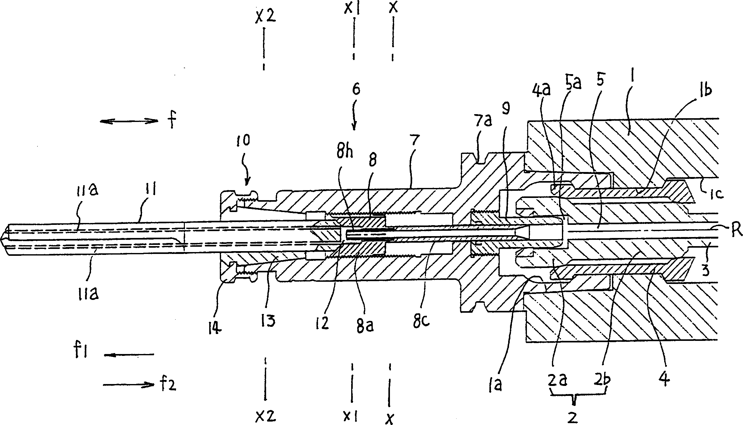
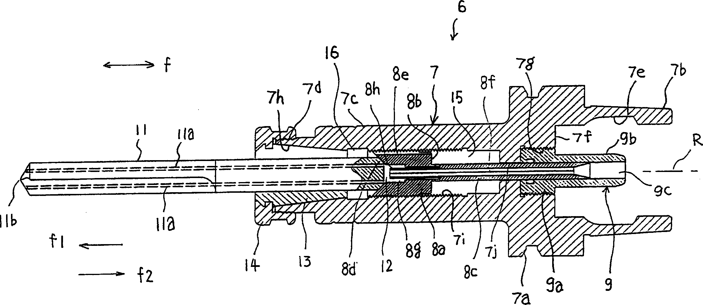
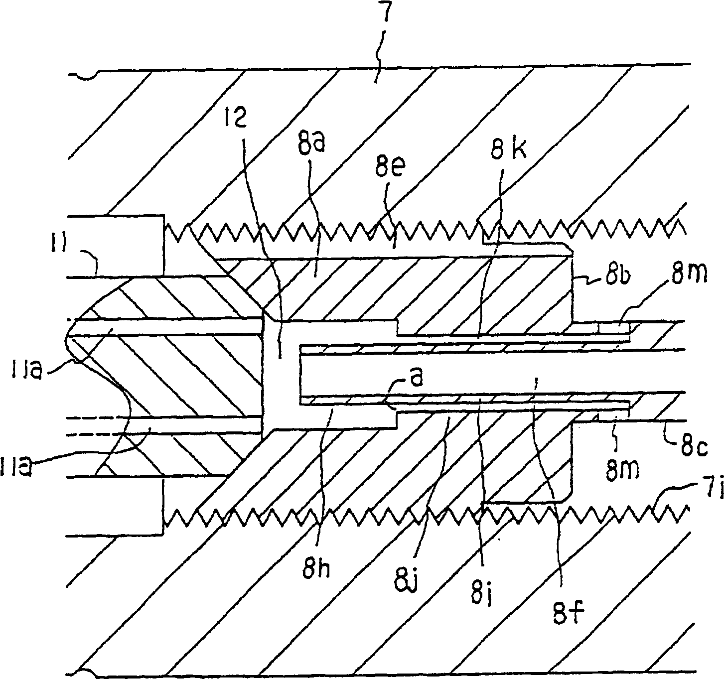
[0035] figure 1 A side sectional view showing an embodiment of a spindle device of a machine tool provided with the tool holder, figure 2 It is a side sectional view of the aforementioned tool holder, image 3 is an enlarged cross-sectional view of the periphery of the tool receiving assembly of the aforementioned tool holder, Figure 4 express figure 1 Sectional view of x-x in, Figure 5 express figure 1 Sectional view of x1-x1 in, Image 6 express figure 1 Sectional view of x2-x2 in.

[0036] In the above figure, 1 is the main shaft of the machine tool, and a tapered hole 1a or a pair of parallel holes 1b, 1c are formed at the rotation center R of the main shaft 1 . In addition, a cylindrical clamping portion 2 composed of a large diameter portion 2a and a small diameter portion 2b and a tie rod portion 3 for displacing the clamping portion in the front-rear d...


PUM


Abstract

A tool holder of a machine tool, wherein a holder rear end part is fixed to the front end part of the spindle of the machine tool, a tool receiving surface part (8d) for receiving the rear end face of a shaft-like tool (11) fixed to a holder front end part so that a closed space (12) in contact with the rear end face can be formed and fog cutting fluid passages (8f, 9c) for leading fog cutting fluid fed from the front end part of the spindle to the closed space (12) are formed in a holder body (7) on a rotating center (R), and exhaust passages (8k, 8m, 8e) are formed for opening a part of the tool receiving surface part (8d) in contact with the closed space (12) to the atmosphere, whereby even when the shaft-like tool (11) is small in diameter and the amount of the fog cutting fluid flowing out to the atmosphere through a passage hole (11a) in the shaft-like tool (11) is small, the liquefied cutting fluid can be prevented from being accumulated in the fog cutting fluid passages (8f, 9c) by maintaining the flow velocity of the fog cutting fluid in the fog cutting fluid passages (8f, 9c) at proper levels.

Description

technical field [0001] The present invention relates to a tool holder of a machine tool that sprays mist cutting fluid supplied from a spindle of the machine tool from the tip of a shaft-shaped tool. Background technique [0002] In the machining of machine tools, in order to cool and lubricate the workpiece and tool, or remove chips, a large amount of cutting fluid is supplied to the machining part, but in this way, not only the environmental pollution caused by the cutting fluid but also the human body Adverse effects on health, high cost caused by waste oil treatment of cutting fluid, reduced tool life due to overcooling of the workpiece, or sliding wear of the tool during fine cutting due to excessive cutting fluid, etc. , A large amount of cutting fluid adheres to the chips, so when the chips are processed or reused, the cutting oil attached to them must be separated. [0003] In order to solve these problems, in recent years, there have been so-called dry cutting mach...

Claims


Application Information

Patent Timeline
Patent Type & Authority Applications(China)
IPC IPC(8): B23Q1/00B23Q11/10
CPCY10T408/458Y10T408/455B23Q11/10B23Q1/0018Y10T409/304032B23Q11/1023
Inventor 菅田秦介桢山正
Owner HORKOS
Learn More