
Using method of spiral type crop circulation electric hot air drying device

A drying device and electric hot air technology, applied in the field of crops, can solve the problems of affecting efficiency, low drying efficiency, and production of aflatoxin, and achieve the effects of improving drying efficiency and speeding up flow rate.

Inactive Publication Date: 2017-11-21
魏满妹
View PDF5 Cites 1 Cited by
  • Summary
  • Abstract
  • Description
  • Claims
  • Application Information

AI Technical Summary

Problems solved by technology

If the harvested grains are not dried in time, the grains tend to become soft and have a slight musty smell, and then the chaff is wet and dusty, turning white, producing aflatoxin, which will be poisoned and even fatal after human consumption
The existing grain drying method is to dry the grain by free-falling and accumulating on the bottom of the drying bin. This drying method has a small area of ​​contact with each grain, and there is no way to fully dry each side of the grain, and the drying efficiency is low.
In addition, there is also a device for heating and drying on the transmission surface, which is only provided with a heating plate on the transmission surface, so that the rice can only be heated on one side, not only the heating effect is poor, but also the moisture emitted by the heating cannot be volatilized in time If it is drained away, it will seriously affect the efficiency

Method used


Image

  • Using method of spiral type crop circulation electric hot air drying device
  • Using method of spiral type crop circulation electric hot air drying device
  • Using method of spiral type crop circulation electric hot air drying device

Examples


Embodiment Construction

[0020] The present invention will be further described below in conjunction with the accompanying drawings and embodiments.

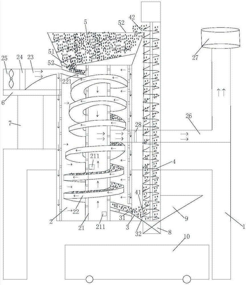
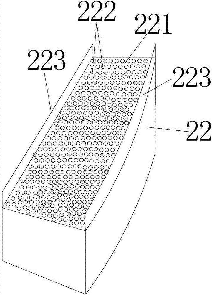
[0021] refer to figure 1 and image 3As shown, a method for using a spiral type grain circulating electric hot air drying device of the present invention is characterized in that: the method provides a spiral type circulating electric hot air drying device, and the spiral type circulating electric hot air drying device includes A support 1, the support is equipped with a dry buffer bin 2, a discharge bin 3 and an auger conveyor 4 whose tank wall is a hollow air outlet structure, and the dry buffer bin 2, discharge bin 3 and auger conveyor 4 are arranged side by side, and the auger conveyor 4 is arranged vertically; a feed bin 5 is arranged on the dry buffer bin 2, and a hollow air guide cylinder 21 is arranged in the center of the dry buffer bin 2, and the hollow guide The wind cylinder 21 is perpendicular to the bottom of the dry buffer bin 2 and the...


PUM


Abstract

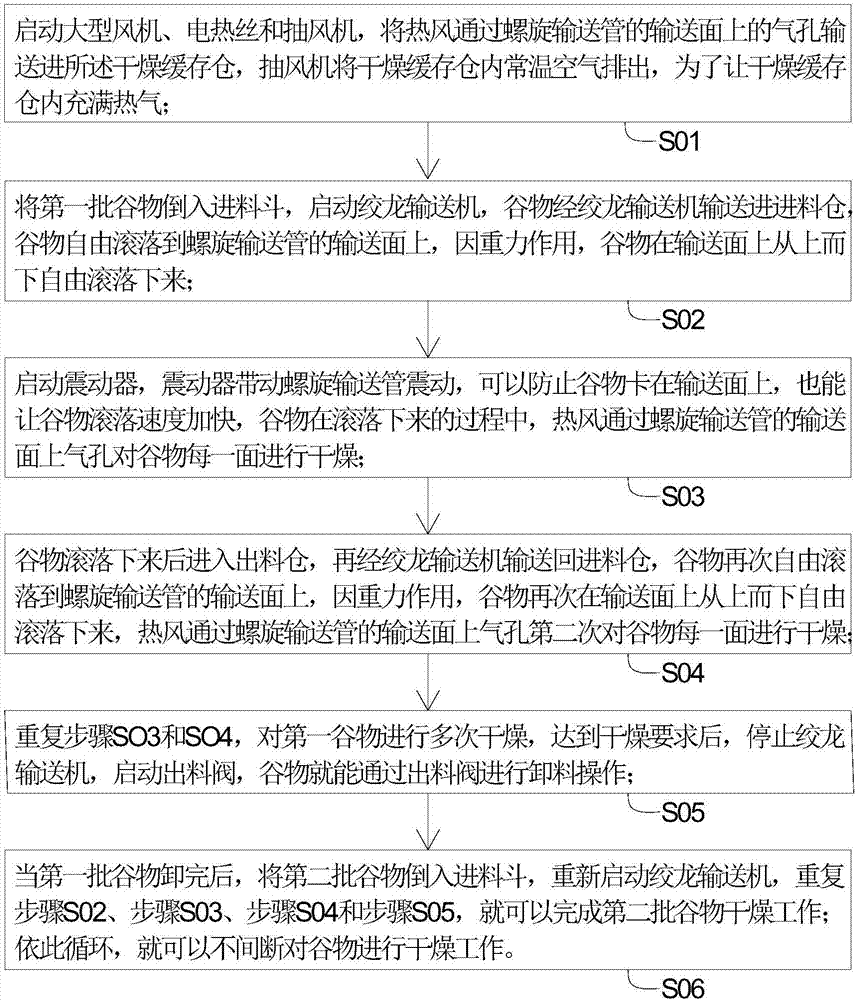
The invention relates to a using method of a spiral type crop circulation electric hot air drying device. The using method is characterized by comprising the steps that S01, a fan, an electric heating wire and an exhaust fan are started, hot air is conveyed into a drying temporary storage bin through air holes in the conveying face of a spiral conveying pipe, and normal-temperature air in the drying temporary storage bin is exhausted out through the exhaust fan so that the drying temporary storage bin can be filled with the hot air; S02, a first batch of crops are poured into a feeding hopper, an auger conveyer is started, the crops are conveyed into a feeding bin through the auger conveyer and freely fall on the conveying face of the spiral conveying pipe, and the crops freely fall on the conveying face from top to bottom under the action of gravity; and S03, a vibrator is started and drives the spiral conveying pipe to vibrate, the crops can be prevented from being stuck on the conveying face, and the falling speed of the crops can be increased. The method fully utilizes the spiral mode, all faces of all the rolling crops are dried through the electric hot air, the crops are fully dried, and the crop drying efficiency is improved.

Description

technical field [0001] The invention relates to the technical field of crops, in particular to a method for using a spiral grain circulation electric hot air drying device. Background technique [0002] Moisture is an important chemical component in grains. Moisture in grains not only has a great influence on the physiology of seeds, but also has a great influence on the processing and storage of grains and the value of grains. If the harvested grains are not dried in a timely manner, the grains tend to become soft and have a slight musty smell, and then the chaff is wet and grayed, turning white, and aflatoxin is produced, which can be poisonous or even fatal to people after eating. The existing grain drying method is to dry the grains by free-falling and accumulating on the bottom of the drying bin. This drying method has a small area of ​​contact with each grain, and there is no way to fully dry each side of the grains, and the drying efficiency is low. In addition, ther...

Claims


Application Information

Patent Timeline
IPC IPC(8): F26B17/12F26B21/00F26B25/00F26B25/04A23B9/08
CPCF26B17/12A23B9/08F26B21/001F26B21/004F26B25/002F26B25/04F26B2200/06
Inventor 魏满妹
Owner 魏满妹
Learn More