
A UAV remote real-time positioning surveying and mapping display interconnected control method

A real-time positioning and control method technology, applied in the field of UAV surveying and mapping, can solve the problems of time axis labeling, poor real-time performance, and inability to associate positions, etc., to improve human-computer interaction, improve surveying and mapping efficiency, and improve information exchange and operation The effect of flexibility

Active Publication Date: 2019-11-15
周超
View PDF4 Cites 0 Cited by
  • Summary
  • Abstract
  • Description
  • Claims
  • Application Information

AI Technical Summary

Problems solved by technology

[0014] 1. The current aerial survey technology is characterized by high precision and can generate different types of result files in the later stage, such as 3D models, etc., but the real-time performance is not strong. Even if the map can be generated in real time, the drone needs to fly directly above the designated location for aerial survey , it takes a certain amount of time to output the result, and the distance and area cannot be calculated immediately in the first time
[0015] And at present, the UAV defines a target point, must fly directly above the target point, and use its own GPS coordinates as the marking point of the target point, but cannot remotely determine the coordinates of any target point under the camera; The description of the target point is displayed in text on the video screen
[0016] two. At present, UAV networking applications are generally managed in a background server, or one machine is one ground station, and there is no interactive application between UAVs.
[0017] three. At present, the UAV and ground mobile device software record the event of the target point, and it is not marked according to the time axis, nor can it be associated with the location

Method used


Image

  • A UAV remote real-time positioning surveying and mapping display interconnected control method
  • A UAV remote real-time positioning surveying and mapping display interconnected control method
  • A UAV remote real-time positioning surveying and mapping display interconnected control method

Examples


Embodiment Construction

[0051] In order to make the above objects, features and advantages of the present invention more comprehensible, specific implementations of the present invention will be described in detail below. In the following description, numerous specific details are set forth in order to provide a thorough understanding of the present invention. However, the present invention can be implemented in many other ways different from those described here, and those skilled in the art can make similar improvements without departing from the connotation of the present invention, so the present invention is not limited by the specific implementation disclosed below.

[0052] Step 1. Determine the geographic coordinates of the center point of the drone camera:

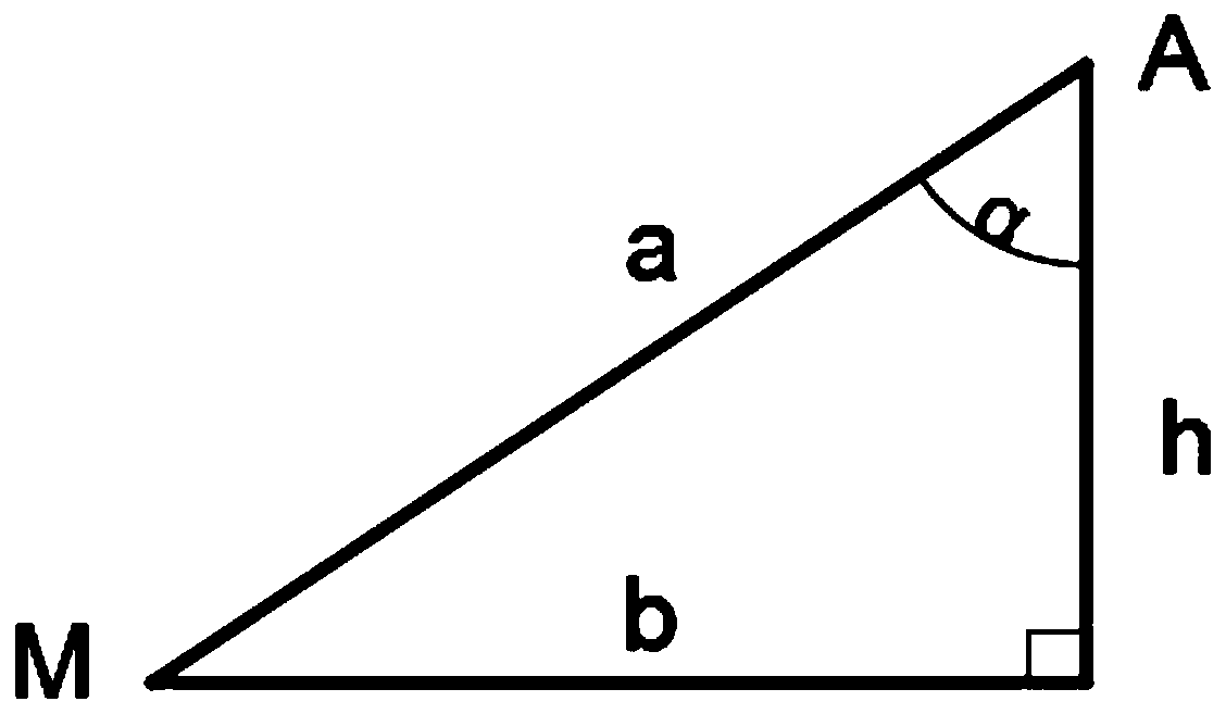
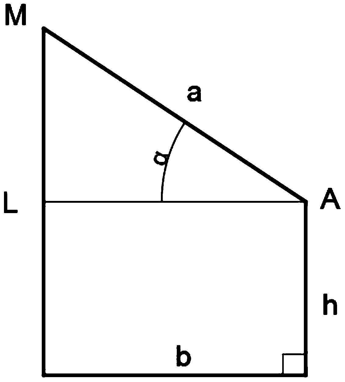
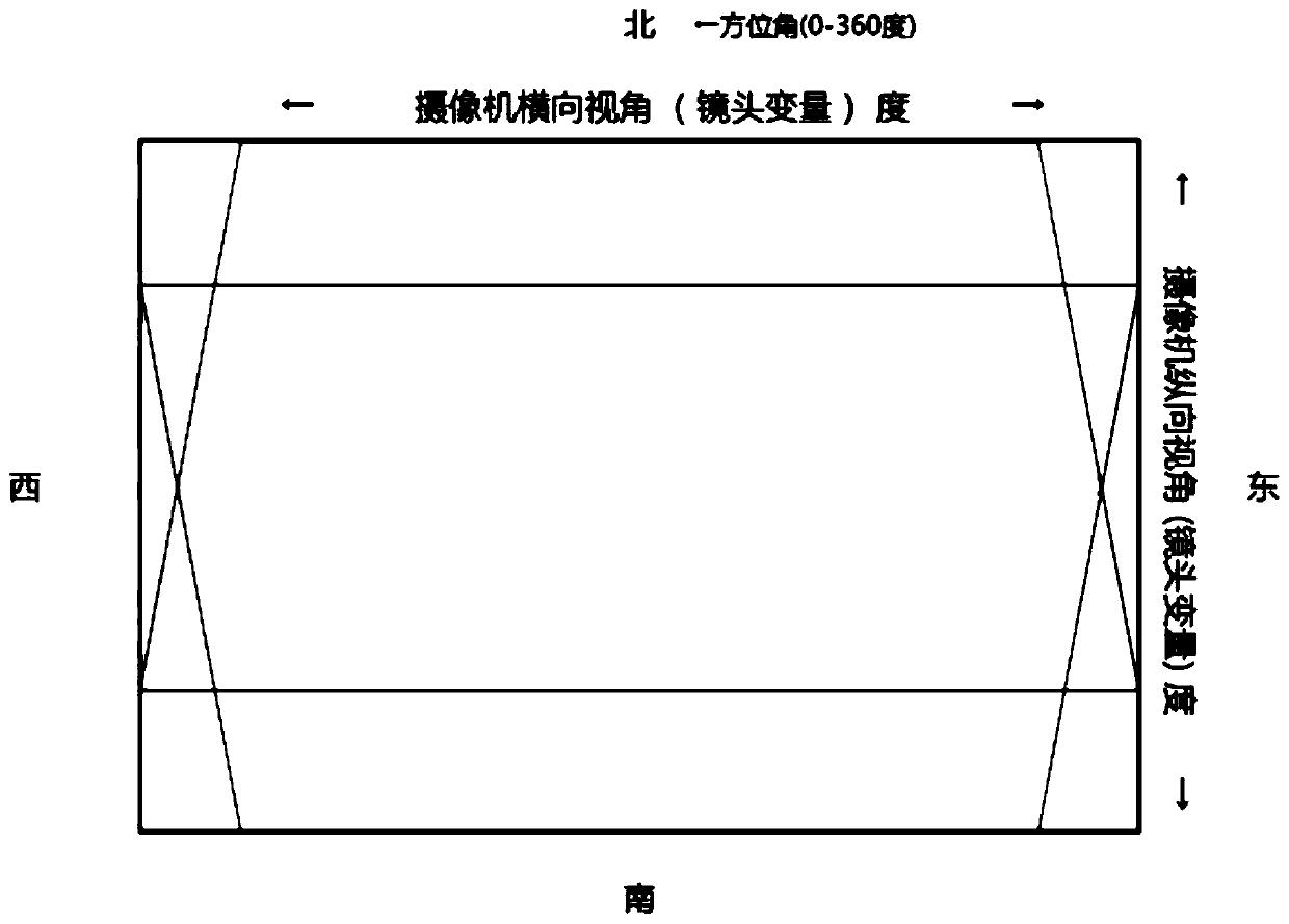
[0053] 1) Determine the basic parameters: determine the latitude and longitude (lng, lat) and altitude h of the location of the drone, and determine the azimuth β and pitch angle α of the camera;

[0054] 2) Determine the altitude of the ...


PUM


Abstract

The invention discloses an unmanned aerial vehicle long-distance real-time positioning mapping display interconnection type control method, which comprises: determining the longitude, the latitude and the altitude of an unmanned aerial vehicle position, and the azimuth angle and the pitch angle of a camera; determining the altitude of a center point and the liner distance between the center point and the upright projection point of the unmanned aerial vehicle on the ground according to the linear distance between the unmanned aerial vehicle and the center point, wherein the linear distance between the unmanned aerial vehicle and the center point is determined by the laser distance measurement instrument on the unmanned aerial vehicle; determining the geographical coordinates of the center point by using a latitude and longitude calculation formula; calculating the true width and the true height of the visual field in the camera image by using a trigonometric function theorem according to the altitude of the unmanned aerial vehicle and the pitch angle, and determining the coordinates of other points by combining with the coordinates of the center point and the screen pixel resolution; and defining multiple marking points, calculating the distances between different marking points, and calculating the area of the polygon formed from the marking point by using a Heron's formula. According to the present invention, with the method, the positioning of the geographical coordinates of the any target point in the long-distance real-time video can be achieved, the altitude is determined, and the visual field area is determined.

Description

technical field [0001] The invention belongs to the technical field of unmanned aerial vehicle surveying and mapping, and specifically relates to an interconnected control method for remote real-time positioning, surveying and mapping display of an unmanned aerial vehicle. Background technique [0002] The application of drones in the field of surveying and mapping mainly uses drones to quickly obtain large-scale high-resolution images of the survey area. The spatial resolution of the acquired images ranges from cm to m, and the surveying and mapping information is fed back to the receiver on the ground. Therefore, all UAVs for surveying and mapping have high-precision digital imaging equipment with adjustable angles and wireless transceiver modules for information. It is suitable for 1:2000 or larger scale topographic map surveying and orthophoto production, and is fully capable of obtaining high-resolution remote sensing image data. After the image is acquired, use the ex...

Claims


Application Information

Patent Timeline
Patent Type & Authority Patents(China)
IPC IPC(8): G01C11/00
CPCG01C11/00
Inventor 周超
Owner 周超
Learn More