
Electrochemistry energy storing device

An energy storage device and electrochemical technology, applied in the field of electrochemistry, can solve the problems of reducing the effective area of ​​the tab connection, increasing the physical resistance of the connection area, reducing the space utilization rate of the battery case, etc., to increase the volumetric energy density, The effect of increasing the connection contact area and improving the utilization rate of internal space

Active Publication Date: 2017-11-21
CONTEMPORARY AMPEREX TECH CO
View PDF5 Cites 4 Cited by
  • Summary
  • Abstract
  • Description
  • Claims
  • Application Information

AI Technical Summary

Problems solved by technology

In this case, since the positive and negative uncoated areas are at both ends of the battery, there will be interlayer misalignment when the positive and negative uncoated areas are respectively connected to the conductive tabs, resulting in dislocation at the tab connection. The effective area is reduced, which increases the physical resistance of the connection area
In order to increase the effective area of ​​the connection, the uncoated area of ​​the positive and negative electrodes must be increased, which reduces the utilization of the battery housing space, thereby reducing the volumetric energy density of the battery

Method used


Image

  • Electrochemistry energy storing device
  • Electrochemistry energy storing device
  • Electrochemistry energy storing device

Examples


Embodiment Construction

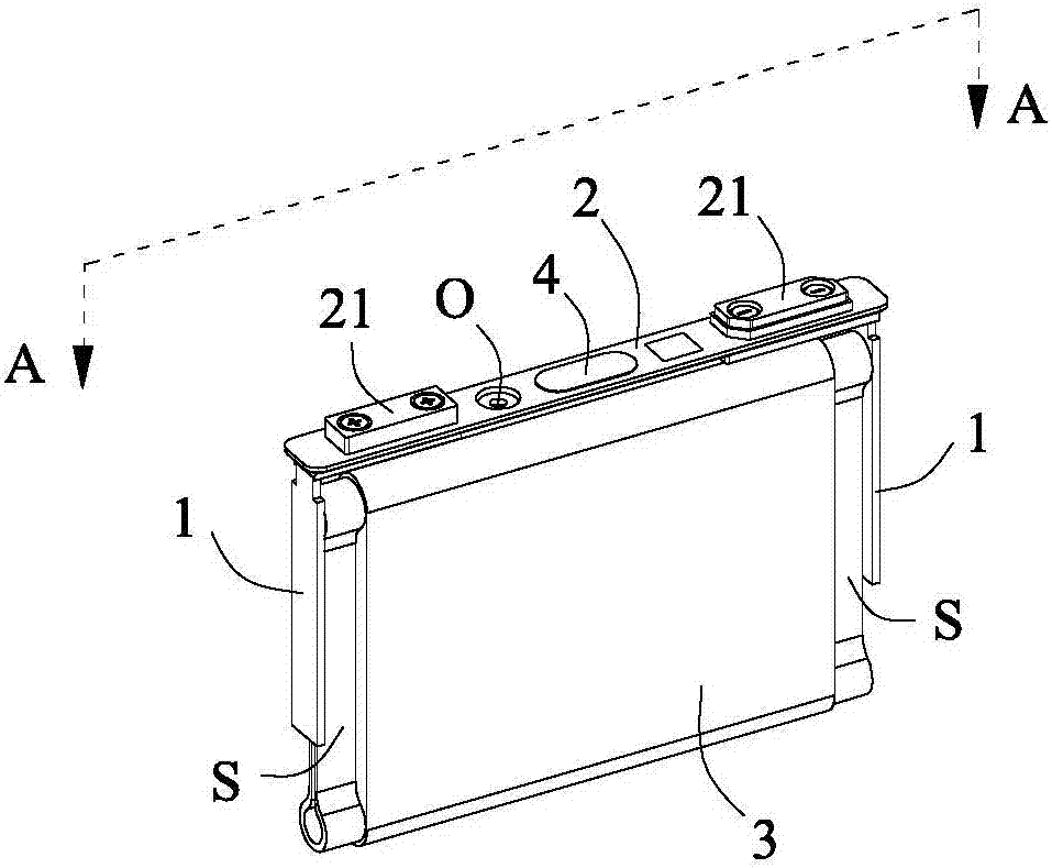
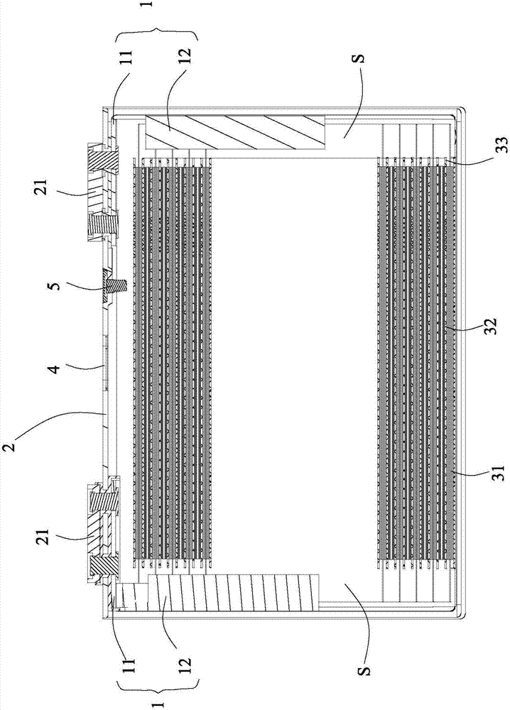
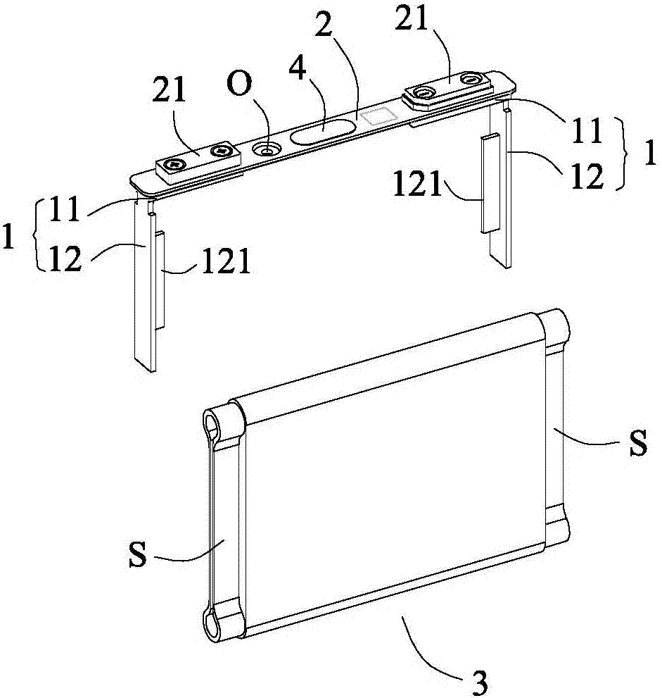
[0029] The electrochemical energy storage device according to the present invention will be described in detail below with reference to the accompanying drawings.

[0030] refer to Figure 1 to Figure 10 , The electrochemical energy storage device according to the present invention includes: a top cover 2, a wound bare cell 3 and two conductive adapters 1 with opposite polarities.

[0031] The top cover 2 is provided with poles 21 with opposite electrical polarities. The wound bare cell 3 has lugs S with opposite electrical polarities. Two conductive adapters 1 with opposite electrical polarities are electrically connected to the poles 21 with opposite electrical polarities of the top cover 2 and the tabs S with opposite electrical polarities of the bare cell 3. Each conductive adapter 1 has: the top cover side connection The part 11 is used to be fixed on the top cover 2 of the electrochemical energy storage device so as to be electrically connected with the pole 21 of the ...


PUM


Abstract

The invention provides an electrochemistry energy storing device, comprising a top cover, a coiling type naked battery cell and two conductive switchover sheets with opposite electric polarities. The top cover is equipped with terminal posts with the opposite electric polarities. The coiling type naked battery cell is equipped with tabs with the opposite electric polarities. The two conductive switchover sheets with the opposite electric polarities are electrically connected with the terminal posts of the top cover with the opposite electric polarities and the tabs of the naked battery cell with the opposite electric polarities. Each conductive switchover sheet is equipped with a top cover side connecting part which is electrically connected with the terminal post on the top cover with the corresponding electric polarity; and a tab side connecting part which stretches from the top cover side connecting part to a direction away from the top cover. A lug boss which projects from the internal surface of the tab side connecting part to the coiling type naked battery cell of the electrochemistry energy storing device, is inserted into an internal space formed by the tab of the coiling type naked battery cell with the corresponding electric polarity, contacts the tab with the corresponding electric polarity and is electrically connected with the tab with the corresponding electric polarity, is formed on the each tab side connecting part. According to the electrochemistry energy storing device, a utilization rate of the internal space is high and the volume energy density is high.

Description

technical field [0001] The invention relates to the field of electrochemistry, in particular to an electrochemical energy storage device. Background technique [0002] Lithium-ion batteries, as a new type of chemical power source, have high energy density and power density, and are increasingly used in the field of electric vehicles. Compared with traditional cars, the mileage of electric vehicles is a key point of concern. Usually, electric vehicles have very limited space for battery packs. In order to obtain higher energy output in a limited space, it is required to upgrade lithium-ion secondary batteries. While increasing the mass energy density, the volume energy density must also be increased. [0003] In the production of lithium-ion secondary batteries for electric vehicles, the commonly used methods to increase the volumetric energy density include the lamination method and the tab die-cutting and winding method. The stacking method can effectively improve the spa...

Claims


Application Information

Patent Timeline
Patent Type & Authority Applications(China)
IPC IPC(8): H01M10/0587H01G11/26H01G11/52
CPCH01M10/0587H01G11/26H01G11/52Y02E60/10Y02P70/50
Inventor 罗广生邱祥云刑承友蒋治亿许金梅
Owner CONTEMPORARY AMPEREX TECH CO
Learn More