High-performance aluminum alloy bridge stand

An aluminum alloy, high-performance technology, applied in the direction of electrical components, etc., can solve the problem of poor dust-proof and heat-dissipating performance of the bridge

Inactive Publication Date: 2017-11-21
镇江昌达电气有限公司
View PDF0 Cites 0 Cited by
  • Summary
  • Abstract
  • Description
  • Claims
  • Application Information

AI Technical Summary

Problems solved by technology

The current bridge frame has poor dustproof and heat dissipation performance

Method used


Image

  • High-performance aluminum alloy bridge stand
  • High-performance aluminum alloy bridge stand
  • High-performance aluminum alloy bridge stand

Examples


Embodiment 1

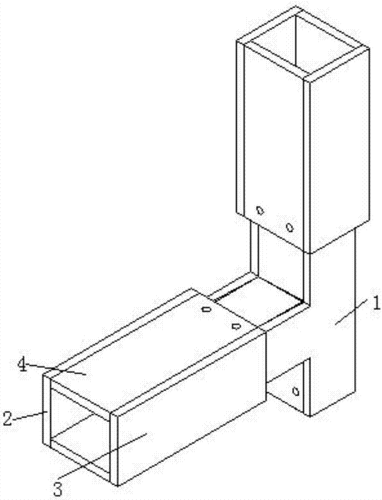
[0034] As shown in the figure, a high-performance aluminum alloy bridge includes two bridge bodies and bridge connectors;

[0035] The bridge connecting piece includes a connecting piece bottom plate, a connecting piece side plate, a connecting piece top plate and a terminal head. The connecting piece side plate is arranged between the connecting piece top plate and the connecting piece bottom plate, and the connecting piece top plate and the connecting piece bottom plate are connected to each other. The side plates of the connecting piece are symmetrical, and the bottom plate of the connecting piece and the top plate of the connecting piece are both "T"-shaped structures. The connecting piece side plate includes the first test board, the second test board, the third test board, the fourth test board and the fifth test board. A first connecting end, a second connecting end and a third connecting end are formed between the bottom plate of the connecting piece, the side plate of the...

Embodiment 2

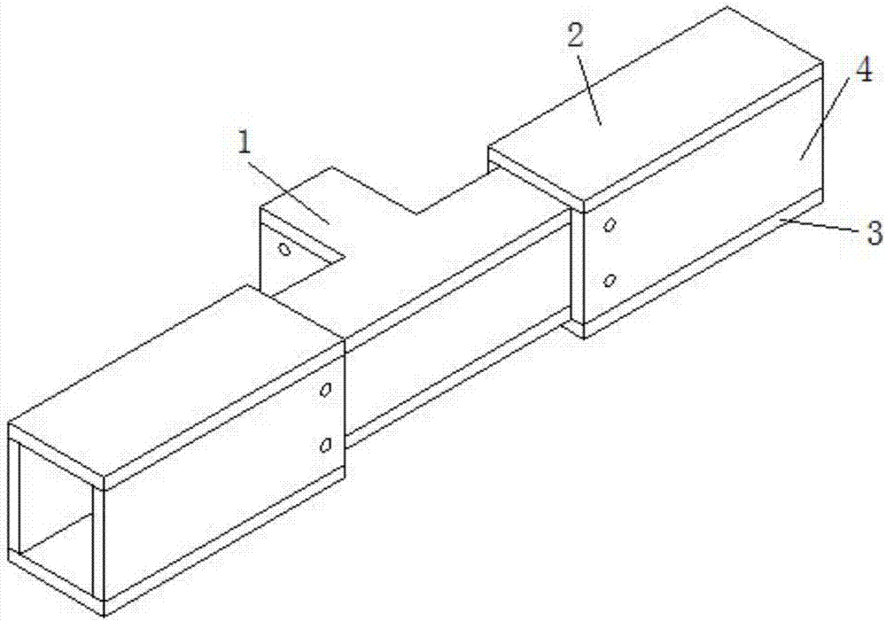
[0043] As shown in the figure, a bridge connector for a bridge frame. The difference from Embodiment 1 is that the terminal head is set at the second connection end through the first connector; the two bridge bodies are set at the second connection end through the second connector. A connecting end and a third connecting end, and the second connecting member is a second bolt and a second nut.

Embodiment 3

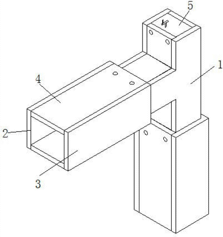
[0045] As shown in the figure, a bridge connector for a bridge frame. The difference from Embodiment 1 is that the terminal head is set at the third connecting end through the first connector; the two bridge bodies are set at the second connector through the second connector. A connecting end and a second connecting end, and the second connecting member is a second bolt and a second nut.

[0046] The invention can control the rotation of the turntable through a hand crank. When the vents on the turntable coincide with the vents on the first sealing plate, ventilation and heat dissipation can be realized. When the vents on the turntable coincide with the vents on the first sealing plate When staggered, it can be sealed and dustproof, and the position of the terminal head is optional, which can play a role of straight or curved.


PUM


Abstract

The invention provides a high-performance aluminum alloy bridge, which includes two bridge bodies and bridge connectors. The bridge connectors include connector bottom plates, connector side plates, connector top plates and terminal heads. The connector side The plates are arranged between the top plate of the connector and the bottom plate of the connector, the top plate of the connector and the bottom plate of the connector are symmetrical about the side plates of the connector, the terminal head includes a first plate, a second plate and a sealing plate, and the sealing plate includes a first One plate, the second plate and the third plate; the present invention can control the rotation of the turntable through the hand handle, and when the vent on the turntable coincides with the vent on the first plate, ventilation and heat dissipation can be realized. When the ventilation opening on the turntable is staggered from the ventilation opening on the first sealing plate, the sealing and dustproof can be realized. The position of the terminal head is optional, which can play the role of straight-through or bend-through.

Description

Technical field [0001] The invention relates to the field of power supply and distribution, in particular to a high-performance aluminum alloy bridge frame. Background technique [0002] As a common support and protection device for cable laying in the power supply system of electrical equipment, cable trays protect and guide the cables laid in the cable tray. Traditional cable trays are mainly divided into trough type, ladder type, tray type and net format structure. [0003] The trough type bridge is a rigid structure system with tightly connected and supporting cables composed of straight sections, bends, components, support arms, hangers, etc. of pallets or ladders. The current bridge has poor performance in dust and heat dissipation. Summary of the invention [0004] In order to solve the problems in the prior art, the present invention provides a high-performance aluminum alloy bridge. [0005] The technical solution of the present invention to solve the above problems is: a ...

Claims


Application Information

Patent Timeline
IPC IPC(8): H02G3/04H02G3/03
CPCH02G3/0406H02G3/03
Inventor 郭力嘉郭如海崔正生
Owner 镇江昌达电气有限公司
Why Eureka
Try Eureka