Computer host heat dissipation device based on wind speed and pressure principle

A technology of a heat sink and a computer, which is used in computing, electrical digital data processing, digital processing power distribution, etc., can solve the problem of not being able to completely isolate dust, etc., and achieve the effect of novel design

Pending Publication Date: 2019-06-07
HUNAN UNIV OF SCI & ENG
View PDF0 Cites 1 Cited by
  • Summary
  • Abstract
  • Description
  • Claims
  • Application Information

AI Technical Summary

Problems solved by technology

[0004] In the use of computers, the heat dissipation of the computer mainframe is an important factor affecting the running speed of the computer. The air inlet of the existing computer mainframe is always open, and it is easy to blow dust into the inside of the mainframe when there is wind outside. Although it is equipped with a dust-proof net, But it can't completely isolate the dust

Method used


Image

  • Computer host heat dissipation device based on wind speed and pressure principle
  • Computer host heat dissipation device based on wind speed and pressure principle
  • Computer host heat dissipation device based on wind speed and pressure principle

Examples


Embodiment 1

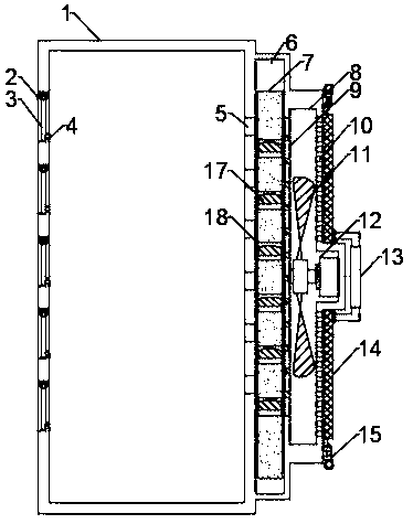
[0027] In the embodiment of the present invention, a computer mainframe cooling device based on the principle of wind speed and pressure includes a mainframe casing 1, an air outlet 2 arranged on the side end of the mainframe casing 1 for hot gas discharge, and an air outlet 2 arranged on the mainframe casing 1 and connected to the air outlet. 2 The blast chamber 8 at the opposite position for the entry of new gas; the left and right ends of the blast chamber 8 are respectively provided with a fan outlet 9 and a fan inlet 10, and a useful The movable cavity 6 placed on the light movable plate 7, the movable cavity 6 is communicated with the inner side of the host casing 1 through the air inlet 5 of the main engine, the movable cavity 6 is communicated with the blast chamber 8 through the air outlet 9 of the fan, and the blower 8 cools the outside temperature The lower air is transported into the host shell 1 through the movable chamber 6, and the gas with a higher temperature i...

Embodiment 2

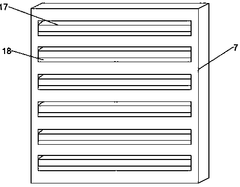
[0036] The present invention also provides another embodiment to improve the present application. Specifically, the difference between the second embodiment and the first embodiment is that the height of the inner cavity of the movable cavity 6 is greater than the height of the lightweight movable plate 7, and Sliding up and down on the lightweight movable plate 7, the lightweight movable plate 7 is provided with a plurality of through grooves 18, the end of the through grooves 18 away from the blast chamber 8 is arranged horizontally, and the end of the through groove 8 that fits the blast chamber 8 is inclined Shaped and parallel to the fan outlet 9, the fan outlet 9 is also inclined, the through groove 18 and the host air inlet 5 are staggered up and down, and the blast chamber 8 blows the gas obliquely upwards to the light through the fan outlet 9. The movable plate 7, when the gas passes through the horizontal end on the through groove 18, makes the horizontal plate 17 hav...


PUM


Abstract

The invention relates to the technical field of computer heat dissipation, in particular to a computer host heat dissipation device based on the wind speed and pressure principle, which comprises a host shell, an air outlet formed in the side end of the host shell and used for discharging hot air, and an air blowing cavity formed in the host shell, opposite to the air outlet and used for allowingfresh air to enter, a fan air outlet and a fan air inlet are formed in the left end and the right end of the air blowing cavity correspondingly. A movable cavity used for containing a light movable plate is formed between the air blowing cavity and the host shell, the light movable plate capable of sliding up and down relative to the movable cavity is arranged on the inner side of the movable cavity, and a plurality of through grooves are formed in the light movable plate and are parallel to the fan air outlet. The movable cavity is formed between the air blowing cavity and the host shell, thelight movable plate is slidably mounted in the movable cavity, and the light movable plate moves upwards under the action of wind power in the air blowing cavity, so that a through groove in the light movable plate communicates with the inner side of the host shell to achieve ventilation and heat dissipation.

Description

technical field [0001] The invention relates to the technical field of computer heat dissipation, in particular to a computer host heat dissipation device based on the principle of wind speed and pressure. Background technique [0002] A computer, commonly known as a computer, is a modern electronic computing machine used for high-speed computing. It can perform numerical calculations, logical calculations, and has storage and memory functions. It is a modern intelligent electronic device that can run according to the program and process massive data automatically and at high speed. [0003] Composed of hardware systems and software systems, computers without any software installed are called bare metal. It can be divided into five categories: supercomputers, industrial control computers, network computers, personal computers, and embedded computers. More advanced computers include biological computers, photonic computers, and quantum computers. [0004] In the use of comp...

Claims


Application Information

Patent Timeline
Patent Type & Authority Applications(China)
IPC IPC(8): G06F1/20G06F1/18
Inventor 包本刚万李刘志壮罗哲肖磊
Owner HUNAN UNIV OF SCI & ENG
Why Eureka
Try Eureka