
Multi-channel controllable output filter device

An output filtering and output terminal technology, which is applied in the field of multi-channel controllable output filtering devices, can solve the problems that IGBT devices are difficult to meet the requirements of kilowatt power, the contactor is large in size, and has poor compatibility, and achieves good electromagnetic compatibility effect and heat dissipation area. Great, reduce the effect of electromagnetic radiation

Pending Publication Date: 2017-11-21
CHONGQING DAJI ELECTRONICS TECH
View PDF6 Cites 4 Cited by
  • Summary
  • Abstract
  • Description
  • Claims
  • Application Information

AI Technical Summary

Problems solved by technology

[0002] When using high-current and high-power equipment, due to the limitation of power or current, the contactor corresponding to the power is usually selected as the switching component, but the contactor is large in size, and its internal mechanical structure will be broken at the moment of contact when the switch operates. In the case of ignition, electromagnetic radiation will be generated, which will not be used in an environment with high requirements for electromagnetic radiation; it is difficult to use a single IGBT device to meet the requirements of kilowatt power, and the cost is high. Different power requirements need to be configured with switches of corresponding power sizes Devices are inconvenient to use and have poor compatibility; in order to prevent the negative impact of external electromagnetic interference on electronic equipment, filtering units are usually installed inside electronic equipment; but in actual use, the cables connected from the power supply to each electronic equipment It will become the absorption source of electromagnetic interference; in order to solve the above problems, it is necessary to conduct in-depth research

Method used


Image

  • Multi-channel controllable output filter device
  • Multi-channel controllable output filter device
  • Multi-channel controllable output filter device

Examples


Embodiment Construction

[0014] The technical solutions in the present invention will be further described below in conjunction with the accompanying drawings and embodiments.

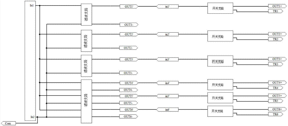
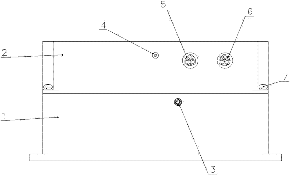
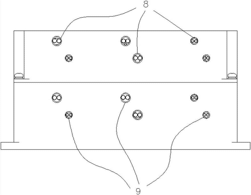
[0015] A multi-channel controllable output filter device, including a shielding case, such as figure 2 , image 3 As shown, the shielding case includes a lower cover 1 and an upper cover 2, and the upper cover 2 and the lower cover 1 are fixedly connected to each other by screws 7; a filter circuit board and a switch circuit board are arranged in the shielding case, wherein the lower cover 1 It is fixedly connected with the switch circuit board, and the upper cover 2 is fixedly connected with the filter circuit board; there are six switch branches on the switch circuit board, and the switch branches include controllable switch circuits, and four filter circuits are arranged on the filter circuit board. Branch road; such as figure 1 As shown, the positive input terminals of each filter branch are connected in parallel and co...


PUM


Abstract

The invention provides a multi-channel controllable output filter device. The device includes a shielding shell which is internally provided with a filter circuit board and a switch circuit board. The filter circuit board is provided with a plurality of filter branches. The switch circuit board is provided with a plurality of switch branches. The positive input ends of the filter branches are connected in parallel, and are connected with a positive input wiring end. The negative input ends of the filter branches are connected in parallel, and are connected with a negative input wiring end. The positive / negative output ends of the filter branches are connected with the input ends of the switch branches in a one-to-one correspondence manner. The negative / positive output ends of the filter branches are connected with negative / positive switch output wiring ends in a one-to-one correspondence manner. Each switch branch includes a controllable switch circuit. The control ends of the controllable switch circuits are connected with control wiring pins in a one-to-one correspondence manner. A control common wiring end is connected with the negative input ends of the filter branches or the negative switch output wiring ends. The multi-channel controllable output filter device is suitable to be used as a high-power load switch, and has good electromagnetic compatibility.

Description

technical field [0001] The invention relates to the technical field of filtering, in particular to a multi-channel controllable output filtering device. Background technique [0002] When using high-current and high-power equipment, due to the limitation of power or current, the contactor corresponding to the power is usually selected as the switching component, but the contactor is large in size, and its internal mechanical structure will be broken at the moment of contact when the switch operates. In the case of ignition, electromagnetic radiation will be generated, which will not be used in an environment with high requirements for electromagnetic radiation; it is difficult to use a single IGBT device to meet the requirements of kilowatt power, and the cost is high. Different power requirements need to be configured with switches of corresponding power sizes Devices are inconvenient to use and have poor compatibility; in order to prevent the negative impact of external el...

Claims


Application Information

Patent Timeline
Patent Type & Authority Applications(China)
IPC IPC(8): H02M1/44H05K9/00
CPCH02M1/44H05K9/0007
Inventor 杨雨泰梁异荣汪文峰任添翔朱韦翰
Owner CHONGQING DAJI ELECTRONICS TECH
Learn More