Assembly-type building greenery wall

A prefabricated, green wall technology, applied in the direction of buildings, building components, building structures, etc., can solve the problem of pedestrians who are easy to get wet, and achieve the effect of avoiding excessive humidity

Inactive Publication Date: 2017-11-24
广东弘信建设有限公司
View PDF7 Cites 6 Cited by
  • Summary
  • Abstract
  • Description
  • Claims
  • Application Information

AI Technical Summary

Problems solved by technology

[0006] And when the above-mentioned water spraying phenomenon occurs in the planters on the upper floors, the water droplets will be sprayed downward in large quantities in multiple directions, and it is easy to wet the pedestrians downstairs.

Method used


Image

  • Assembly-type building greenery wall
  • Assembly-type building greenery wall
  • Assembly-type building greenery wall

Examples


Embodiment 1

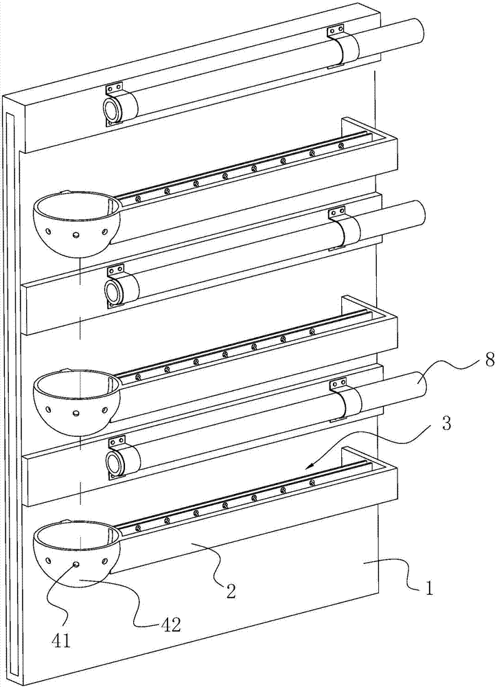
[0058] Embodiment 1, prefabricated building green wall, such as figure 1 As shown, a prefabricated wall panel 1 is included, and the wall panel 1 is hollow.

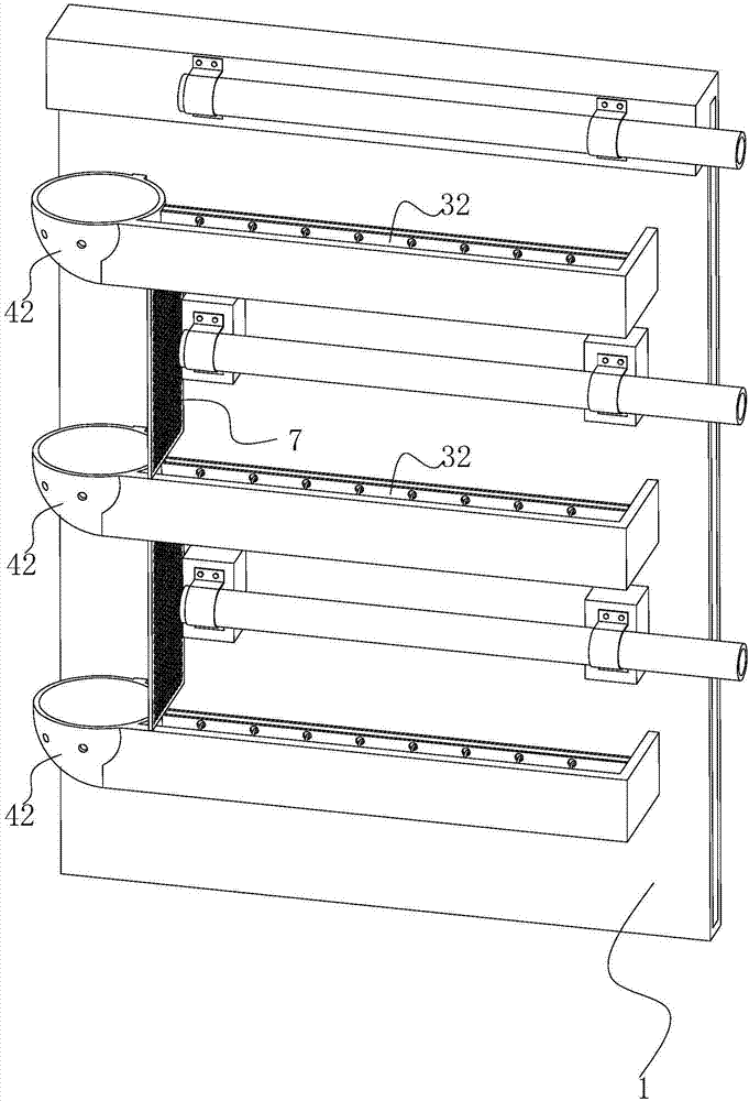
[0059] The side of the wall panel 1 is integrally formed with three connecting plates 2, which are poured and formed in the factory according to the mold. The connecting plates 2 are arranged horizontally, and the connecting plates 2 arranged up and down are all parallel to each other.

[0060] The connection plate 2 is provided with concave flower tanks 3, the flower tanks 3 are used for planting vegetation, and the upper end of each flower tank 3 is provided with a water spray pipe 8, and each water spray pipe 8 supplies water to each flower tank 3 independently.

[0061] One end of the planter 3 is provided with a guide surface 42 whose outer wall is hemispherical, and the guide surface 42 protrudes downward.

[0062] The lowest end of the diversion surface 42 is facing the opening of the flower tank 3 below, and the...

Embodiment 2

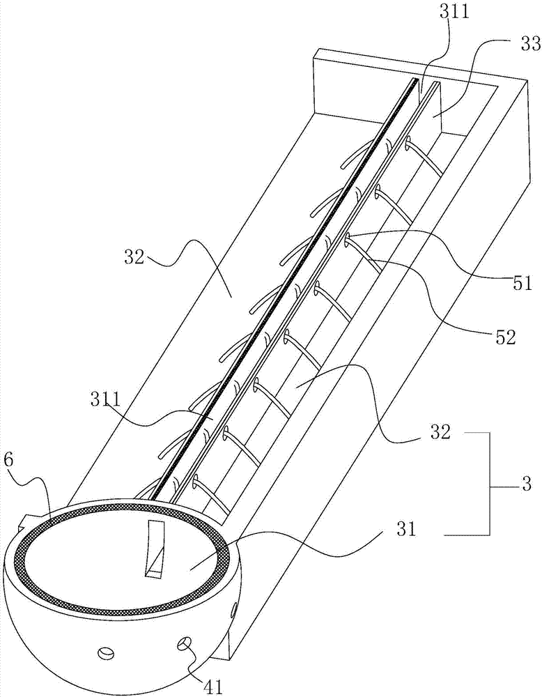
[0069] Embodiment 2, its difference with embodiment 1, such as figure 2 As shown, a partition 33 is arranged in the planter 3, and there are two partitions 33. Each partition 33 includes a straight plate and an arc-shaped plate, and the straight plate and the arc-shaped plate are fixedly connected to each other. There is a gap between the two partitions 33. , while the upper ends of the two curved plates are connected to each other. The partition 33 divides the planter 3 into a water tank 31 and a planting tank 32 , and the overflow hole 41 is placed on the wall of the water tank 31 ; and the height of the partition 33 is higher than that of the overflow hole 41 . The height of the planting tank 32, the height of the dividing plate 33, and the height of the overflow hole 41 are successively reduced so that the water flow can flow into the water tank 31 through the planting tank 32 to accumulate, and the water exceeding the volume of the water tank 31 can have an overflow hole...

Embodiment 3

[0075] Embodiment 3, a kind of prefabricated building green wall, its difference with embodiment 1 or embodiment 2, such as Figure 4 As shown, the guide surface 42 adopts a conical surface.


PUM


Abstract

The invention discloses an assembly-type building greenery wall. The greenery wall solves the problem that when a water spraying phenomenon of an upstairs flower trough happens, water droplets are sprayed in large quantities in many directions and then wet pedestrians downstairs. According to the technical scheme, the greenery wall comprises a prefabricated wall plate, a plurality of connecting plates are arranged on the side surface of the wall plate, and a connecting plate is provided with the flower trough; the flower trough is provided with an overflow hole, and the outer wall of the flower trough is provided with a smooth flow guide surface; the flow guide surface is connected to the external port of the overflow hole, and the lower end of the flow guide surface is positioned directly opposite to the flower trough below the flow guide surface. Flow in the overflow hole flows along the flow guide surface and slides to drop into the subjacent flower trough from a fixed point, and therefore overflowed water is received through multiple layers, so that the conditions of flow spraying in large quantities are reduced.

Description

technical field [0001] The invention relates to a building wall panel, more specifically, it relates to a prefabricated building green wall. Background technique [0002] With the development of the construction industry, house construction has begun to transform into house manufacturing. [0003] The so-called building body manufacturing means that the wall panels of the house are completed in advance in the factory. After the building skeleton is formed on the construction site, the finished wall panels are transported to the construction site and assembled on the building skeleton in an assembled manner. Wall panel assembly technology can greatly shorten the molding cycle of real estate. [0004] A Chinese patent document with the announcement number CN205637849U has been retrieved. Its patent name is a prefabricated greenery composite wall. It is recorded in the plan that it includes prefabricated wall panels. The drip irrigation system regularly waters the vegetation ...

Claims


Application Information

Patent Timeline
IPC IPC(8): A01G9/02A01G25/02A01G27/06E04C2/30
CPCA01G9/023A01G25/02A01G27/06E04C2/46
Inventor 李锐标李燕慧叶晓楠
Owner 广东弘信建设有限公司
Why Eureka
Try Eureka