
Anti-static floor for construction of weal current machine room

An anti-static floor and reinforcing plate technology, which is applied to local raised floors, buildings, building structures, etc., can solve the problems of affecting the installation efficiency of anti-static floors, increasing the labor intensity of staff, and the cumbersome and inconvenient installation process. The effect of convenience and efficiency, reducing labor intensity and ensuring stability

Inactive Publication Date: 2020-07-10
马鞍山方融信息科技有限公司
View PDF0 Cites 1 Cited by
  • Summary
  • Abstract
  • Description
  • Claims
  • Application Information

AI Technical Summary

Problems solved by technology

[0004] The purpose of the present invention is to solve the problem that the anti-static floor in the prior art needs to be fixed with a large number of screws during installation, which makes the installation process too cumbersome and inconvenient, affects the installation efficiency of the anti-static floor, and increases the labor intensity of the staff at the same time. And proposed a kind of anti-static floor for the construction of weak electric room

Method used


Image

  • Anti-static floor for construction of weal current machine room
  • Anti-static floor for construction of weal current machine room
  • Anti-static floor for construction of weal current machine room

Examples


Embodiment Construction

[0024] The following will clearly and completely describe the technical solutions in the embodiments of the present invention with reference to the accompanying drawings in the embodiments of the present invention. Obviously, the described embodiments are only some, not all, embodiments of the present invention.

[0025] In describing the present invention, it should be understood that the terms "upper", "lower", "front", "rear", "left", "right", "top", "bottom", "inner", " The orientation or positional relationship indicated by "outside", etc. is based on the orientation or positional relationship shown in the drawings, and is only for the convenience of describing the present invention and simplifying the description, rather than indicating or implying that the referred device or element must have a specific orientation, so as to Specific orientation configurations and operations, therefore, are not to be construed as limitations on the invention.

[0026] refer to Figure ...


PUM


Abstract

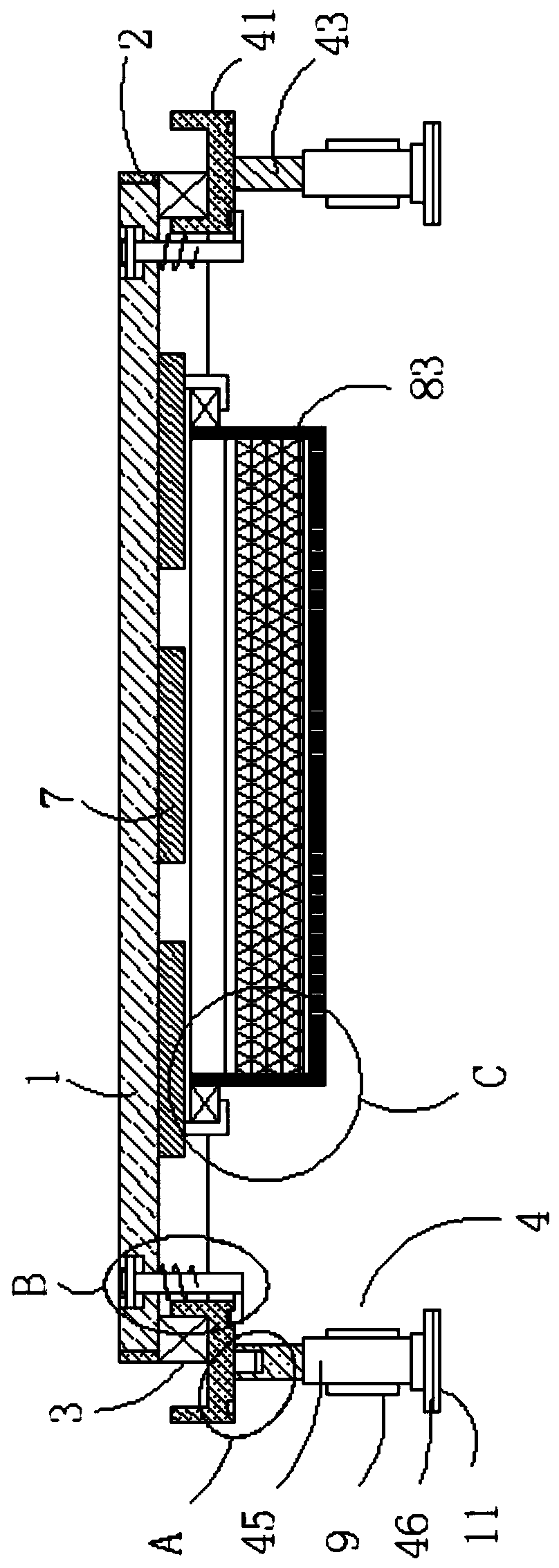
The invention relates to the technical filed of floors, and discloses an anti-static floor for the construction of a weak current machine room. The anti-static floor comprises an anti-static floor body, a side frame is movably connected to the side wall of the anti-static floor body, a supporting frame is fixedly connected to the lower surface of the side frame, a plurality of supporting mechanisms are movably connected to the outer wall of the corner of the supporting frame, grooves are correspondingly formed in four corners of the upper surface of the anti-static floor body, through holes are formed in the inner walls of the grooves, limiting mechanisms are movably connected to the hole walls of the through holes, a plurality of reinforcing plates are fixedly connected to the inner wallof the supporting frame, the upper surfaces of the multiple reinforcing plates are correspondingly and movably connected with the lower surface of the anti-static floor body, and moisture-proof mechanisms are fixedly connected to the lower surfaces of the multiple reinforcing plates. According to the anti-static floor, the convenience and effiency of the installation of the anti-static floor in the weak current machine room can be effectively improved, meanwhile the labor intensity of the staff is lowered, and the moisture removal ability of the anti-static floor can be improved.

Description

technical field [0001] The invention relates to the field of floor technology, in particular to an antistatic floor used in the construction of weak electric room. Background technique [0002] Anti-static floor, also known as dissipative static floor, is a floor that enables the charge to dissipate when it is grounded or connected to any lower potential point, with a resistance between 10 to the 9th power of 10 ohms Space is the characteristic, "GB50174-2008 Code for Design of Electronic Information System Computer Room" Section 8.3.1 on page 20 stipulates: the surface resistance or volume resistance of the anti-static floor or ground should be 2.5×10⁴~1.0×10⁹Ω, and the anti-static technology for weak electric room It is a part of the safety and protection category of the computer room. The problems caused by static electricity are not only difficult for hardware personnel to detect, but sometimes software personnel mistakenly believe that they are software failures, result...

Claims


Application Information

Patent Timeline
IPC IPC(8): E04F15/024E04F15/18
CPCE04F15/02405E04F15/02447E04F15/02464E04F15/181E04F2290/04E04F2290/048
Inventor 刘东王娜
Owner 马鞍山方融信息科技有限公司
Learn More