Honey collector

A collector and honey technology, applied in the field of honey collectors, can solve the problems of slow flow, sticking to the inner wall of the centrifuge, and inability to stir it, so as to achieve the effect of speeding up the collection

Active Publication Date: 2017-11-24
徐州中伦光伏材料有限公司
View PDF11 Cites 11 Cited by
  • Summary
  • Abstract
  • Description
  • Claims
  • Application Information

AI Technical Summary

Problems solved by technology

[0004] The above-mentioned patent also has the following technical problems: 1. After the honey is thrown out, it will stick to the inner wall of the centrifuge. Due to the high viscosity of the honey, the flow is very slow, and it is impossible to speed up the collection of honey; 2. In the prior art Breeding bees are usually outdoors. When using a centrifuge, the centrifuge is transported to the side of the hive, and the honey just taken out is collected directly, and then the frame is put into the hive; generall

Method used


Image

  • Honey collector
  • Honey collector

Examples


Embodiment Construction

[0028] The present invention will be described in further detail below by means of specific embodiments:

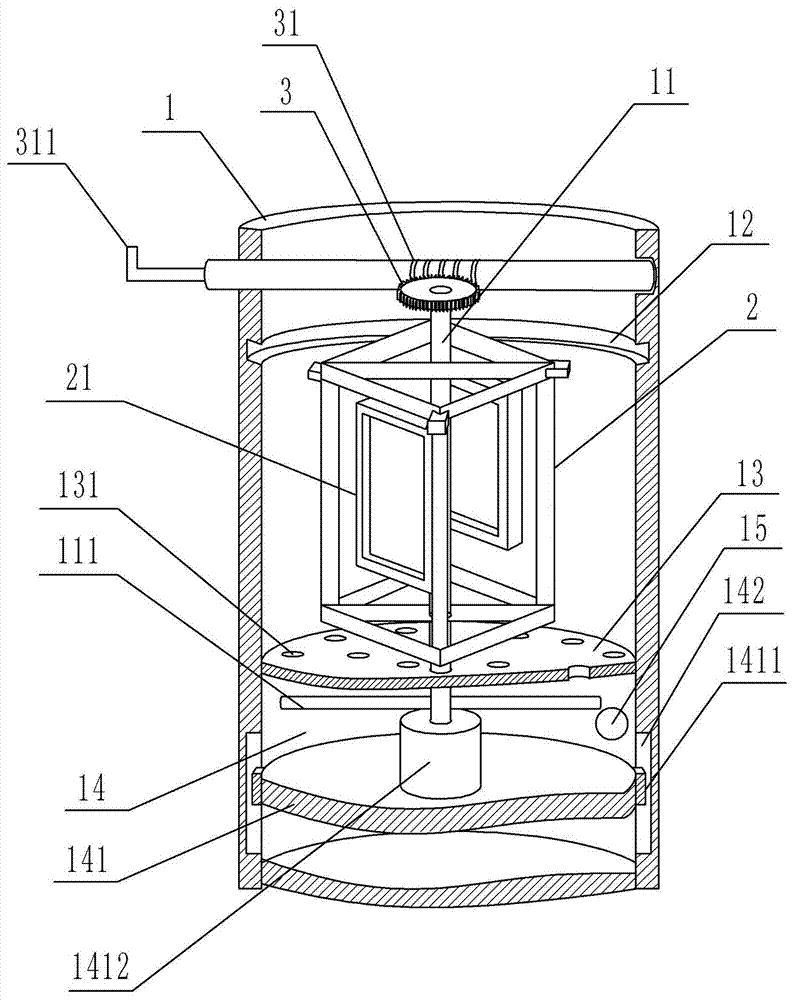
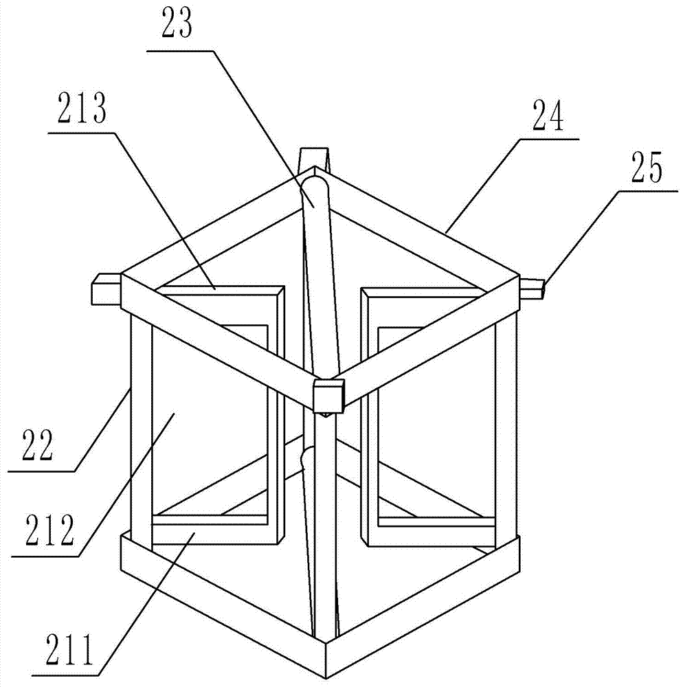
[0029] The reference numerals in the accompanying drawings of the description include: collection barrel 1, rotating rod 11, stirring rod 111, annular limiting groove 12, partition plate 13, suction hole 131, collecting chamber 14, piston 141, limiting protrusion 1411, Strip opening 142, connecting pipe 1412, pick-and-place opening 15, rotating part 2, placement frame 21, square frame body 211, ejection opening 212, insertion opening 213, fixing rod 22, connecting rod 23, square frame 24, limit bar 25, worm gear 3, worm screw 31, handle 311.

[0030] Such as figure 1 and figure 2 As shown, the honey collector includes a collection barrel 1, a rotating part 2 and a power part; the collecting barrel 1 is provided with a rotating rod 11 driven by the power part to rotate forward or reversely, and the inner wall of the collecting barrel 1 is provided with a handle for limi...


PUM


Abstract

The invention relates to the technical field of honey collection, in particular to a honey collector. The honey collector comprises a collecting barrel, a rotary part and a power part and is characterized in that a rotary rod which is driven by the power part to rotate forwardly and reversely is arranged in the collecting barrel, and the inner wall of the collecting barrel is provided with an annular limit groove for preventing the rotary part from moving vertically; the rotary part is connected to the rotary rod, placing frames for placing honeycomb frames are hinged to the rotary part, and the middle of each placing frame is provided with a toss-out opening; a partition provided with a plurality of air suction holes is located below the rotary part; a collecting cavity is formed between the partition and the bottom surface of the collecting barrel; a piston is arranged in the collecting cavity and provided with limit protrusions, and the wall of the collecting cavity is provided with strip-shaped openings; a connecting pipe is fixedly connected to the piston, and the lower portion of the rotary rod is connected with the connecting pipe in a threaded manner; the rotary rod is further provided with a stirring rod; the wall of the collecting cavity is provided with a taking and placing opening with a cover. The honey collector has the advantages that honey collecting speed can be increased, and honey can be stirred.

Description

technical field [0001] The invention relates to the technical field of honey collection, in particular to a honey collector. Background technique [0002] Traditional beekeepers keep bees in beehives. When collecting honey, they pull out the partitions of the beehives and send the partitions into centrifuges to harvest honey. The whole process is time-consuming and laborious, and inevitably disturbs the life of bees; in the past, this It is unimaginable for most beekeepers. They have to wear strict protective clothing, walk into the smoky hive to remove the board covered with honey, and then move out the thick collecting board, scrape off the honey on it, and proceed The next step of processing is very troublesome. [0003] Notification number is that the Chinese patent of CN202876961U just discloses a kind of centrifuge that throws off honey, has realized the collection to honey; The direction of operation can be changed by pushing with hands in the bucket, and the effect...

Claims


Application Information

Patent Timeline
IPC IPC(8): A01K59/00B01F7/16
CPCA01K59/00B01F27/11B01F27/80
Inventor 侯忠华
Owner 徐州中伦光伏材料有限公司
Why Eureka
Try Eureka