Bilateral frame positioning and punching device

A punching device and frame technology, applied in welding equipment, laser welding equipment, metal processing equipment, etc., can solve problems such as processing errors, unevenness, and inability to guarantee the same circle center, so as to shorten the punching time and ensure the punching Accuracy, improved productivity and the effect of punching quality

Pending Publication Date: 2017-11-24
湖北天明粮油设备有限公司
View PDF8 Cites 0 Cited by
  • Summary
  • Abstract
  • Description
  • Claims
  • Application Information

AI Technical Summary

Problems solved by technology

However, with the continuous progress and development of science and technology in our country, the existing mechanical equipment is becoming more and more large-scale, and people are increasingly unable to be satisfied with single-sided drilling.
Especially for the frame used to install the main shaft in mechanical equipment, the two holes located on both sides of the frame with a long distance must be equal in size and concentric. On the one hand, drilling, boring, reaming and turning Holes, etc., after processing the holes on one side of the frame, it is often necessary to manually move the frame or move the processing device to process the holes on the other side of the frame; on the other hand, because the bottom surface of the frame may There are machining errors that lead to unevenness, and it is impossible to guarantee that the two holes on both sides of the frame are concentric with each other when processing after moving the machine frame or moving the processing device

Method used


Image

  • Bilateral frame positioning and punching device
  • Bilateral frame positioning and punching device

Examples


Embodiment Construction

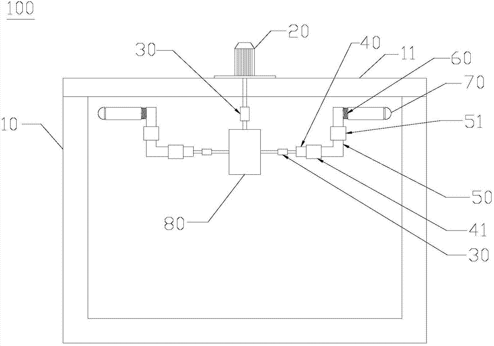
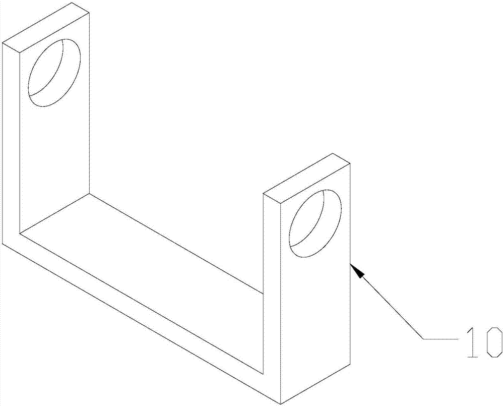
[0028] The following is attached Figure 1-2 The principles and features of the present invention are described, and the examples given are only used to explain the present invention, and are not used to limit the scope of the present invention. In the following paragraphs the invention is described more specifically by way of example with reference to the accompanying drawings. Advantages and features of the present invention will be apparent from the following description and claims. It should be noted that all the drawings are in a very simplified form and use imprecise scales, and are only used to facilitate and clearly assist the purpose of illustrating the embodiments of the present invention.

[0029] It should be noted that when a component is said to be "fixed" to another component, it can be directly on the other component or there can also be an intervening component. When a component is said to be "connected" to another component, it may be directly connected to ...


PUM


Abstract

The invention relates to a bilateral frame positioning and punching device which is used for punching two sides of a frame. The device comprises a driving part, a double-output-shaft steering box and two groups of punching mechanisms, the driving part is fixed on a positioning platform of the frame, an output end of the driving part is fixedly connected with an input end of the double-output-shaft steering box, two output ends of the double-output-shaft steering box are fixedly connected with the punching mechanisms, each group of punching mechanisms comprise cross rods, vertical rods and laser transmitters, the output ends of the double-output-shaft steering box are fixedly connected with the cross rods, the cross rods are fixed with the vertical rods, the vertical rods are fixed with the laser transmitters, and one side of the frame is punched by the laser transmitters. According to the positioning and punching device, the punching mechanisms are simultaneously driven, so that two sides of the frame are punched in a laser manner, manual carrying of the frame or movement of a machining device is avoided, adverse effects of unevenness of the bottom surface of the frame are eliminated, concentricity of two holes in two sides of the frame can be completely ensured, and production efficiency and punching quality are improved.

Description

technical field [0001] The invention relates to a punching device, in particular to a positioning punching device on both sides of a frame. Background technique [0002] Most of the punching devices used in mechanical processing equipment are only single-side punching devices, that is, punching one by one, and mostly adopt methods such as drilling, boring, reaming and turning holes. However, with the continuous progress and development of my country's science and technology, the existing mechanical equipment is becoming more and more large-scale, and people are increasingly unable to be satisfied with single-sided drilling. Especially for the frame used to install the main shaft in mechanical equipment, the two holes located on both sides of the frame with a long distance must be equal in size and concentric. On the one hand, drilling, boring, reaming and turning Holes, etc., after processing the holes on one side of the frame, it is often necessary to manually move the fra...

Claims


Application Information

Patent Timeline
Patent Type & Authority Applications(China)
IPC IPC(8): B23K26/38B23K26/10
CPCB23K26/103B23K26/38
Inventor 郑仁明
Owner 湖北天明粮油设备有限公司
Why Eureka
Try Eureka