
Wave restraining plate assembly for square water tank and installing method of wave restraining plate assembly

A wave plate and water tank technology, which is applied in the field of wave suppression plate components for square water tanks and its installation, and in the field of wave suppression plates for water tanks. It can solve problems such as solder joint pull-off, insufficient strength of wave suppression plates, and complicated installation of wave suppression plates. , to achieve the effect of reducing the stress on solder joints, saving after-sales costs, and increasing its own strength

Inactive Publication Date: 2017-11-24
CRRC NANJING PUZHEN CO LTD
View PDF8 Cites 1 Cited by
  • Summary
  • Abstract
  • Description
  • Claims
  • Application Information

AI Technical Summary

Problems solved by technology

[0006] After analysis, the main reason for the water leakage accident was the insufficient strength of the wave suppressor plate, which caused the solder joints to pull off. Therefore, it is imperative to redesign the wave suppressor plate of the water tank.
Chinese patent CN203543964U discloses "an aluminum alloy water tank for EMUs" although a solution is proposed, but the installation of the wave suppression plate is complicated and only suitable for small water tanks

Method used


Image

  • Wave restraining plate assembly for square water tank and installing method of wave restraining plate assembly
  • Wave restraining plate assembly for square water tank and installing method of wave restraining plate assembly
  • Wave restraining plate assembly for square water tank and installing method of wave restraining plate assembly

Examples


Embodiment Construction

[0030] In order to make the purpose and technical solutions of the embodiments of the present invention more clear, the technical solutions of the embodiments of the present invention will be clearly and completely described below in conjunction with the drawings of the embodiments of the present invention. Apparently, the described embodiments are some, not all, embodiments of the present invention. Based on the described embodiments of the present invention, all other embodiments obtained by persons of ordinary skill in the art without creative efforts shall fall within the protection scope of the present invention.

[0031] Those skilled in the art can understand that, unless otherwise defined, all terms (including technical terms and scientific terms) used herein have the same meaning as commonly understood by those of ordinary skill in the art to which this invention belongs. It should also be understood that terms such as those defined in commonly used dictionaries shoul...


PUM


Abstract

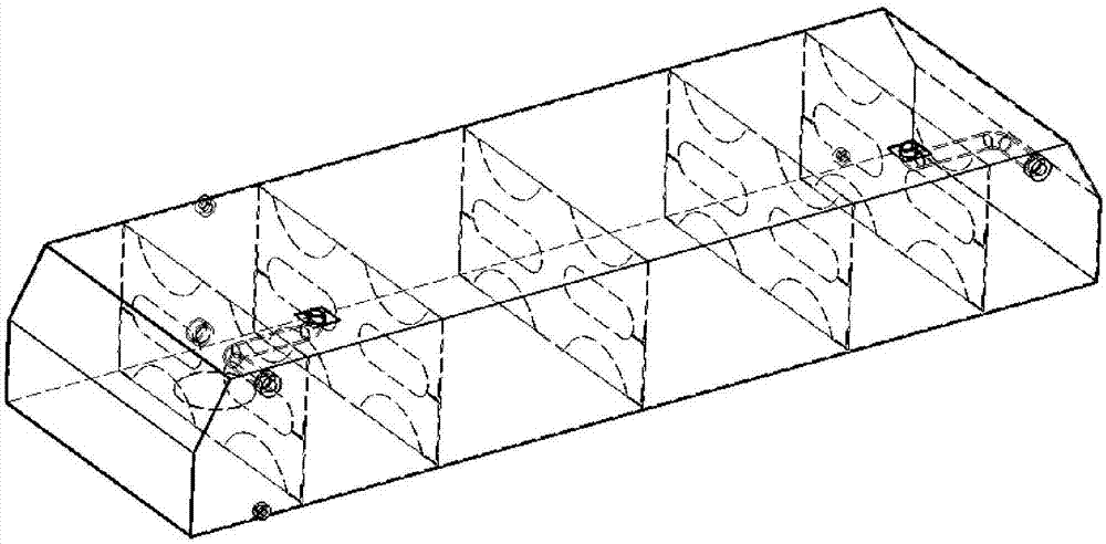
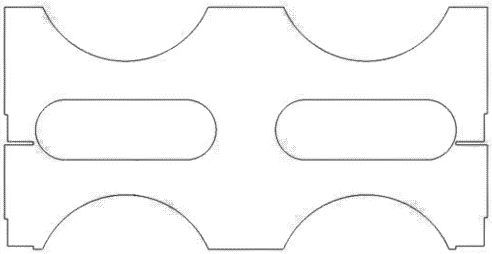
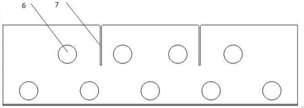
The invention belongs to the field of water tank wave restraining, and relates to a wave restraining plate for a water tank, in particular to a wave restraining plate assembly for the square water tank and an installing method of the wave restraining plate assembly. The wave restraining plate assembly comprises a first longitudinal wave restraining plate body, a second longitudinal wave restraining plate body and a transverse wave restraining plate body; the first longitudinal wave restraining plate body is installed on the bottom face of the square water tank in the longitudinal direction of the square water tank; the second longitudinal wave restraining plate body is installed on the top face of the square water tank in the longitudinal direction of the square water tank and is arranged in correspondence with the first longitudinal wave restraining plate body; one end of the transverse wave restraining plate body in the longitudinal direction is installed on the first longitudinal wave restraining plate body in a plug-in manner, and the other end of the transverse wave restraining plate body in the longitudinal direction is installed on the second longitudinal wave restraining plate body in a plug-in manner; and the square water tank is jointly divided by the first longitudinal wave restraining plate body, the second longitudinal wave restraining plate body and the transverse wave restraining plate body into a plurality of communicated containing cavities. The strength of the wave restraining plate is effectively improved, the deformation amount of the wave restraining plate is reduced, welding points are protected, the water leakage probability of the water tank is reduced, and the service life of the water tank is prolonged.

Description

technical field [0001] The invention belongs to the field of wave suppression for water tanks, and relates to a wave suppression plate for a water tank, in particular to a wave suppression plate assembly for a square water tank and an installation method thereof. Background technique [0002] The square water tank is mainly used for drinking and sanitary water supply in railway passenger cars, and is an important passenger service facility on board. In the past two years, there have been frequent water leakage accidents in large railway square water tanks. [0003] At present, the existing square water tank structure is as follows: figure 1 As shown, the cause analysis of the leakage of the existing square water tank: [0004] 1. The anti-wave plate is a single piece of 2mm stainless steel plate, without folded edges, and has weak resistance to vertical force; there is a water hole in the middle, but the hole is too large, and the narrowest part of the anti-wave plate is o...

Claims


Application Information

Patent Timeline
IPC IPC(8): B65D90/52
CPCB65D90/52
Inventor 鲁长林陈文杰刘玉弟高尔坚朱超
Owner CRRC NANJING PUZHEN CO LTD
Learn More