Automatic chuck for bundling strip cutting machine

An automatic chuck, cutting and baling machine technology, applied in the direction of winding strips, thin material handling, transportation and packaging, etc., can solve the problems of inaccurate cutting size of cloth rolls, increased material waste, low work efficiency, etc. Reduce the effect of poor cutting results, save fabric, and improve efficiency

Active Publication Date: 2017-11-24
肇庆市祥丰利机械实业有限公司
View PDF6 Cites 5 Cited by
  • Summary
  • Abstract
  • Description
  • Claims
  • Application Information

AI Technical Summary

Problems solved by technology

If the length of the claw is lengthened, the clamping part of the cloth roll will usually be deformed due to the clamping of the claw, and can no longer be used as a normal and qualified bundle material. The material at the end is wasted; and if the clamping force of the jaws is increased, the paper tube inside the cloth roll will be slightly shrunk and deformed inward, and the paper tube will be twisted during rotary cutting, resulting in inaccurate cutting size of the end cloth roll , prone to error;
[0004] 2. For each cutting work, it is necessary to manually operate the chuck to clamp the cloth roll at the beginning and remove the remaining material after cutting, and it is necessary to approach the chuck with hands when getting the remaining material. big security risk

Method used


Image

  • Automatic chuck for bundling strip cutting machine
  • Automatic chuck for bundling strip cutting machine
  • Automatic chuck for bundling strip cutting machine

Examples


Embodiment Construction

[0024] Below with reference to the accompanying drawings, through the description of the implementation examples, the specific embodiments of the present invention, such as the shape, structure, mutual position and connection relationship between each part, the role and working principle of each part, etc., will be further described. detailed instructions.

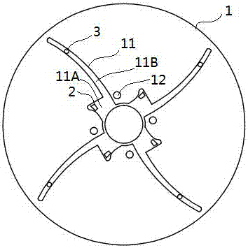
[0025] Such as Figure 1-8 , the automatic chuck for cutting and binding machine of the present invention includes a chuck body 1, the end surface of the chuck body is provided with a track 11 arranged radially outward from the center, and the track 11 includes a gap from the inside to the outside 11A and the slide rail 11B, so that the top jaw 2 that pushes from the center to the outside when the chuck is working is provided in the empty gap 11A, and the clamping arm 3 that is clamped from the outside to the center when the chuck is working is provided in the slide rail 11B. The driving mechanism of the top jaw 2 and the...


PUM


Abstract

The invention provides an automatic chuck for a bundling strip cutting machine, and the automatic chuck is efficient, safe and firm in clamping. The automatic chuck comprises a chuck body. A plurality of tracks which radiate outwards along the center are arranged on the end face of the chuck body. Each track comprises an avoiding notch and a sliding rail from interior to exterior, wherein the avoiding notch is internally provided with an ejector claw ejecting outwards from the center when the chuck works, the sliding rail is internally provided with a clamping arm conducting tight clamping towards the center from the outside when the chuck works. A drive mechanism of each ejector claw and a drive mechanism of each clamping arm are independent of each other. When the automatic chuck works, the clamping arms can be used for rapidly and efficiently clamping the periphery of a cloth roll, the ejector claws are used for ejecting the inner circumferential wall of a paper tube of the cloth roll, and the clamping arms and the ejector claws are driven by air cylinders; and the whole cloth roll fixing process is fast and efficient, clamping is firm, the situation that the human hand gets close to the chuck for operation is not needed, and safety and reliability are achieved.

Description

technical field [0001] The invention relates to the technical field of clothing finishing and ironing machinery, in particular to an automatic chuck for a strip cutting and binding machine. Background technique [0002] Bundle cutting machine is a machine that cuts raw cloth rolls into bundles of specified width according to production requirements. It is widely used in gift packaging, colorful flag making, decorative accessories and other industries. The general cross-sectional structure of cloth roll is as follows: figure 1 As shown, the center of the cloth roll is a paper tube. When cutting the bundles, the paper tube is inserted into the central axis of the bundle cutter, and then one end of the cloth roll is clamped by the claws on the chuck, and then the cloth roll is driven to rotate by the chuck, and then cut. The chuck of the existing strip cutting machine generally adopts the manual universal chuck on the common machine tool, and the outer periphery of the cloth...

Claims


Application Information

Patent Timeline
Patent Type & Authority Applications(China)
IPC IPC(8): B65H16/06
CPCB65H16/06B65H2701/174B65H2701/1842B65H2402/31
Inventor 梁秀娴
Owner 肇庆市祥丰利机械实业有限公司
Why Eureka
Try Eureka