Synchronous transfer device for hosiery machine

A transfer device and hosiery machine technology, applied in textiles, papermaking, knitting, etc., can solve problems such as inability to improve work production efficiency, and achieve the effect of improving efficiency

Pending Publication Date: 2017-11-24
李歆怡
View PDF1 Cites 2 Cited by
  • Summary
  • Abstract
  • Description
  • Claims
  • Application Information

AI Technical Summary

Problems solved by technology

[0004] Aiming at the deficiencies in the prior art, the purpose of the present invention is to provide a synchronous transfer device for hosiery machines to solve the problem of inability to al

Method used


Image

  • Synchronous transfer device for hosiery machine
  • Synchronous transfer device for hosiery machine

Examples


Embodiment Construction

[0018] In order to make the technical means, creative features, goals and effects achieved by the present invention easy to understand, the present invention will be further described below in conjunction with specific embodiments.

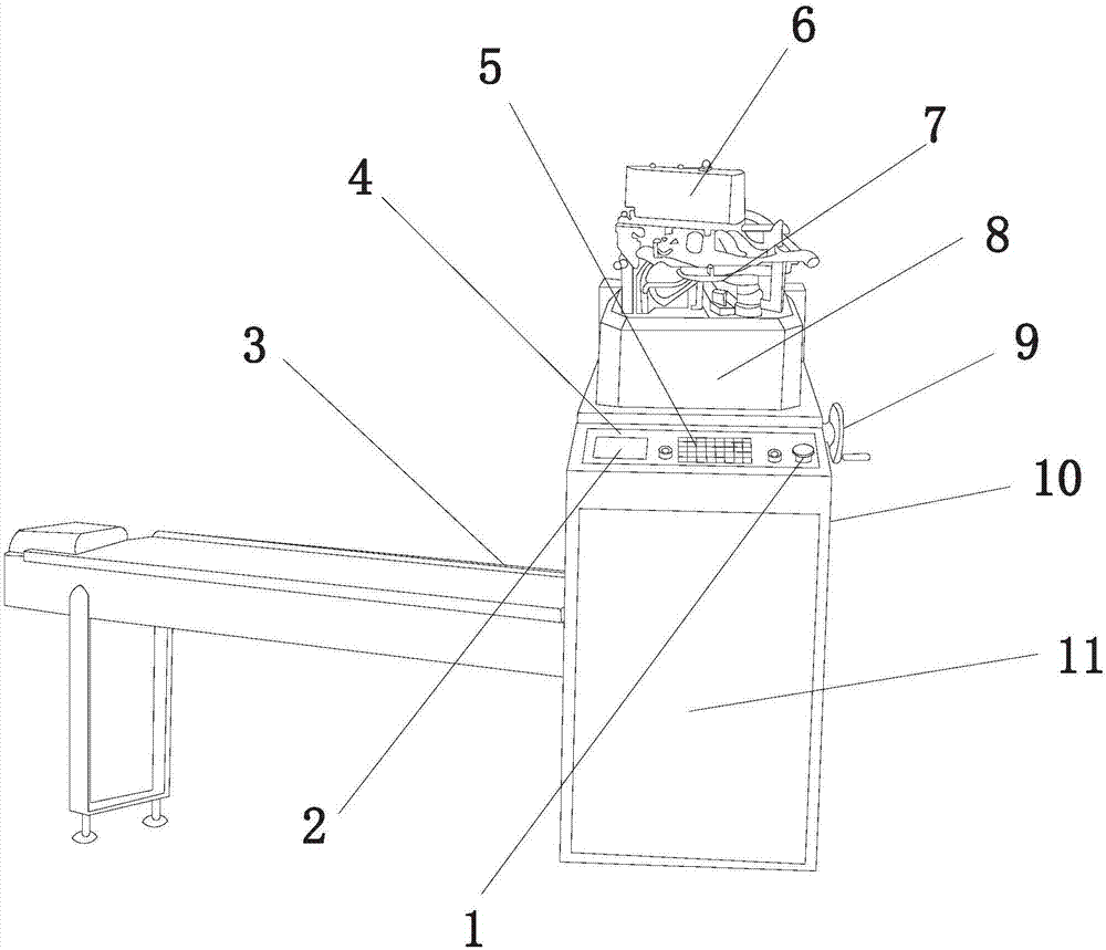
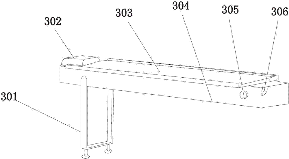
[0019] see figure 1 , figure 2 , the present invention provides a synchronous transfer device for hosiery machine: its structure includes: emergency stop button 1, display screen 2, transmission seat 3, control panel 4, control button 5, transmission shaft box 6, textile main body 7, working Table 8, turntable 9, equipment housing 10, motor cabin 11, the transmission seat 3 is located on the left side of the equipment housing 10, the transmission base 3 is embedded in the motor cabin 11, and the motor cabin 11 is located in the equipment housing 10 The front surface of the device housing 10, the control panel 4 is located on the front surface of the equipment housing 10, the workbench 8 is located on the upper surface of the equipment housing 10...


PUM


Abstract

The invention discloses a synchronous transfer device for a hosiery machine. The structure comprises: an emergency stop button, a display screen, a transmission seat, a control panel, a control button, a transmission shaft box, a textile main body, a workbench, a turntable, and a device casing , motor cabin, support frame, baffle plate, transmission track, transmission casing, transmission shaft, transmission gear, the beneficial effect of the present invention: after using the upper transmission seat on the hosiery machine, the staff can be allowed to sit on both sides, The socks can be inspected along the way, so that the staff can detect the thread ends of the socks and trim them when the socks are driven, without picking up and sending out the socks for inspection, which can improve the efficiency of work and production.

Description

technical field [0001] The invention relates to a synchronous transfer device for hosiery machines, which belongs to the field of hosiery machines. Background technique [0002] Socks machine, in 1589, the British Li invented the first knitting machine, which used crochet to knit shaped socks and produced socks. [0003] The prior art discloses a synchronous transfer device for hosiery machines with the application number: 201521005522.7, which includes: a needle cylinder driving wheel, which is connected to the needle cylinder to drive the needle cylinder to rotate; a long rotating shaft, which is located inside the turret, and The rotation axes of the turret are coaxial, the upper end is connected to the central installation tube through the shaft tube power transmission assembly to drive the rotation of the central installation tube, the lower end is fixed with a meshing gear, and the lower end of the central installation tube is fixed with a transfer head. The head is u...

Claims


Application Information

Patent Timeline
IPC IPC(8): D04B35/00
CPCD04B35/00
Inventor 李歆怡
Owner 李歆怡
Why Eureka
Try Eureka