Municipal telecommunication cable laying fence structure and municipal telecommunication cable laying method

A guardrail structure and cable technology, applied in cable laying equipment, cable installation, cable installation in underground pipes, etc., can solve the problems caused by long distance, large construction time, delaying cable entry time, etc. Reliability and the effect of ensuring signal transmission efficiency

Inactive Publication Date: 2017-11-24
何泽学
View PDF0 Cites 4 Cited by
  • Summary
  • Abstract
  • Description
  • Claims
  • Application Information

AI Technical Summary

Problems solved by technology

[0003] Generally, telecommunication cables need to be pre-embedded in the ground to play a protective role. However, at present, pre-embedding telecommunication cables will cause a problem. Because the pre-embedding needs to dig out the municipal road surface in advance, it will cause damage to the road surface. Causes a greater impact on traffic, so the pre-embedding of telecommunication cables will generate greater safety hazards, causing great pressure on municipal traffic, and causing long distances, resulting in greater construction time and delaying the entry of cables time

Method used


Image

  • Municipal telecommunication cable laying fence structure and municipal telecommunication cable laying method
  • Municipal telecommunication cable laying fence structure and municipal telecommunication cable laying method
  • Municipal telecommunication cable laying fence structure and municipal telecommunication cable laying method

Examples


Embodiment , Embodiment 1

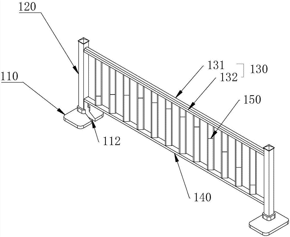
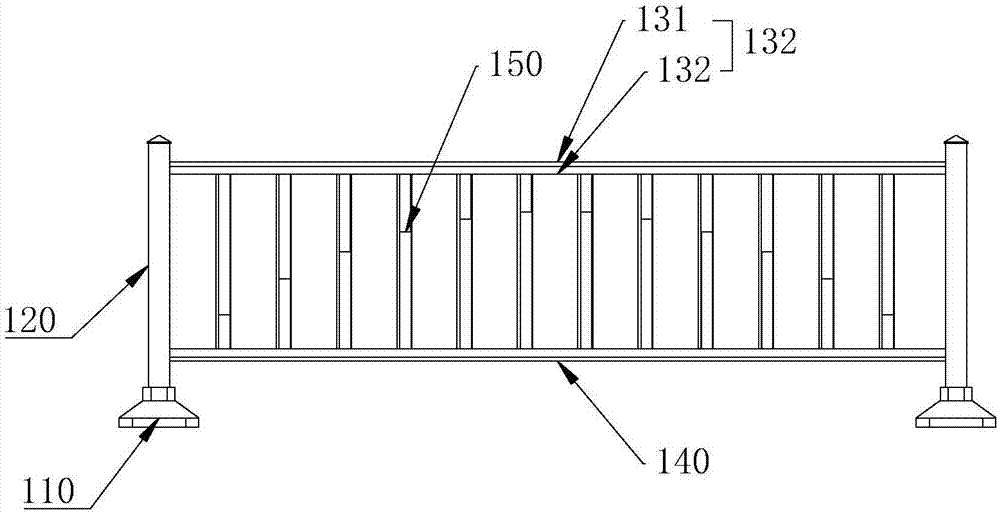
[0071] Regarding the laying of cables, there are the following two embodiments. Embodiment 1, a municipal telecommunication cable laying method, provides the above-mentioned municipal telecommunication cable laying guardrail structure,

[0072] Step A, excavating several installation embedded grooves on the municipal road surface, the two ends of the installation embedded grooves are evenly positioned below the guardrail end;

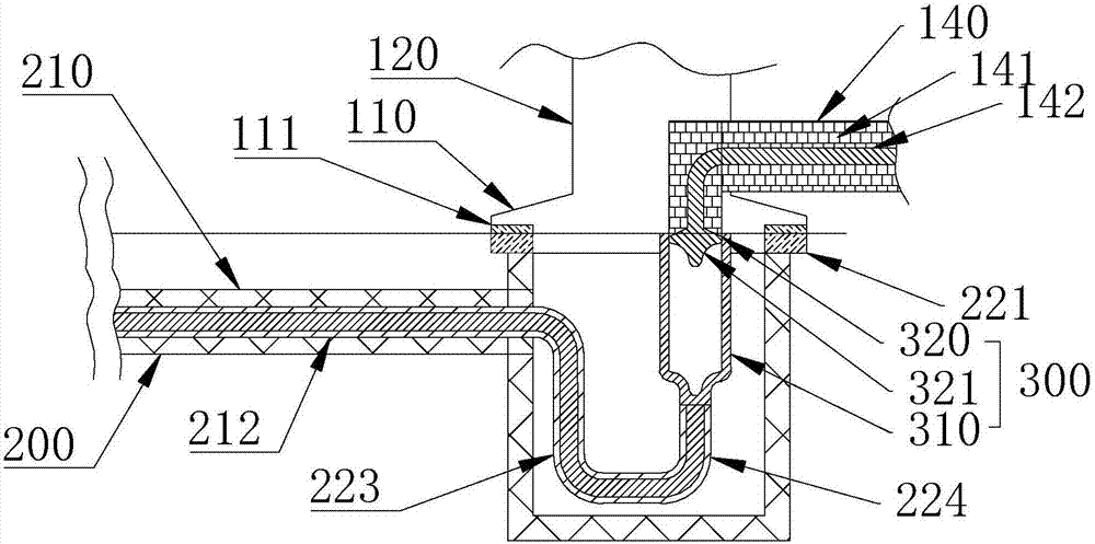
[0073] Step B, installing the buried connection structure 200 into the embedded installation groove and then filling the embedded installation groove;

[0074] Step C, connecting the buried cable body 211 with the placed cable body 142 and connecting the support base 110 of the guardrail section with the buried base of the buried connection structure 200 .

Embodiment 2

[0075] Embodiment 2, a municipal telecommunication cable laying method, provides the above-mentioned municipal telecommunication cable laying guardrail structure,

[0076] Step A, excavating several installation embedded grooves on the municipal road surface, the two ends of the installation embedded grooves are evenly positioned below the guardrail end;

[0077] Step B, installing the buried connection structure 200 into the embedded installation groove and then filling the embedded installation groove;

[0078] Step C, connecting the buried cable body 211 with the placed cable body 142 and connecting the support base 110 of the guardrail section with the buried base of the buried connection structure 200 ;

[0079] Step D, excavating several connecting pre-buried grooves on the municipal road below the guardrail section;

[0080] Step E, pushing the lower cross bar 140 down to the embedded connection groove and then filling the embedded connection groove.


PUM


Abstract

The invention relates to a municipal telecommunication cable laying guardrail structure and its laying method. Firstly, the improved part of the buried connection structure is to set two buried supports. Underground connection structures are required for transition, and in the current situation, most cases have guardrail transitions, so there is no need for excavation on municipal roads with guardrail transitions, and the internal lines can be directly connected by means of guardrail installation. At the same time, through the chute structure set on the support base, the lower cross bar can be slid down when needed, digging the road under the lower cross bar, and gradually completing the cable laying, and even if the lower cross bar is not buried in the ground , can still be connected, and the initial laying is completed. When the time and traffic pressure are a little more generous, the follow-up steps are completed by excavating the road surface, which has the effect of laying, ensuring safety and convenience, greatly improving efficiency and relieving traffic pressure. .

Description

technical field [0001] The invention relates to the technical field of municipal telecommunication cables, and more specifically relates to a municipal telecommunication cable laying guardrail structure and a laying method thereof. Background technique [0002] Telecommunication cable (telecommunication cable) is the transmission line of electrical signals, which is an indispensable transmission medium in various electronic systems. And because of the structure, telecommunication cables are generally composed of conductors, insulation, shielding, sheath and armor. Conductors are used to conduct electrical signals. It should have good electrical properties, sufficient mechanical strength and a certain degree of flexibility. The conductor material is copper, aluminum and other metals with high conductivity. In order to improve the mechanical strength of the micro-miniature cable, copper-clad steel wire or copper alloy is used as the conductor. According to different requir...

Claims


Application Information

Patent Timeline
Patent Type & Authority Applications(China)
IPC IPC(8): E01F15/02E01F15/04H02G9/06H02G1/06
CPCE01F15/02E01F15/04E01F15/0476H02G1/06H02G9/06
Inventor 何泽学
Owner 何泽学
Why Eureka
Try Eureka