
Punning device for electric power engineering construction

A tamping device and electric power engineering technology, which is applied in basic structure engineering, soil protection, construction, etc., can solve the problems of difficult alignment between the heavy hammer and the rod hole, the bulky tamping machine, and the complicated manual tamping process, etc., to reduce labor costs. The effect of labor intensity, simple structure and high degree of automation

Active Publication Date: 2017-11-24
广西电网有限责任公司防城港供电局
View PDF6 Cites 0 Cited by
  • Summary
  • Abstract
  • Description
  • Claims
  • Application Information

AI Technical Summary

Problems solved by technology

In the current electric power engineering construction, two methods of manual compaction and mechanical compaction are usually used for the compaction of the pole pit. The manual compaction process is complicated and time-consuming. Although the compaction machine is very efficient when used in flat areas, there are Problems such as bulky size, inflexible movement, and difficulty in alignment between the heavy hammer and the rod pit

Method used


Image

  • Punning device for electric power engineering construction

Examples


Embodiment Construction

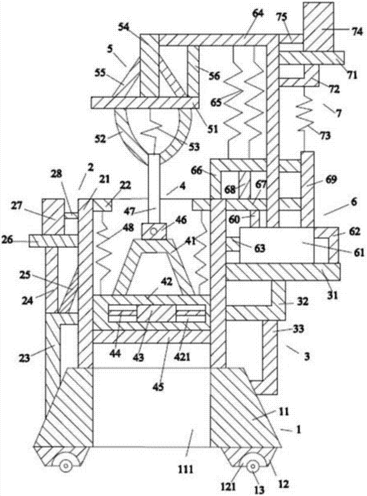
[0020] Such as figure 1 As shown, the tamping device for power engineering construction of the present invention includes a base device 1, a frame device 2 positioned above the base device 1, a bracket device 3 positioned on the right side of the frame device 2, and a frame device housed in the frame device. The smashing device 4 in 2, the connection device 5 above the smashing device 4, the cylinder device 6 above the support device 3 and the counterweight device 7 above the cylinder device 6.

[0021] Such as figure 1As shown, the base device 1 includes a base 11 , a first support block 12 located below the base 11 , and a first roller 13 located below the first support block 12 . The base 11 is a cylinder with an isosceles trapezoidal cross-section. The base 11 is placed horizontally. The base 11 is provided with a square hole 111 passing through its upper and lower surfaces. The square hole 111 is in the shape of a cuboid. The first support block 12 is provided with two ...


PUM


Abstract

A punning device for electric power engineering construction comprises a base device, a frame device, a support device, a tamping device, a connecting device, an air cylinder device and a balance weight device. The base device comprises a base, a first supporting block and a first roller. The frame device comprises a frame body, a first limiting block, a first support, a first supporting rod, a first inclined rod, a first transverse rod, a first balance weight and a second transverse rod, the support device comprises a third transverse rod, a second support and a third support, the tamping device comprises a fourth support, a hammering block, a second balance weight, a fourth transverse rod, a heavy punch, a first fixing block, a first connecting rod and a first spring, the connecting device comprises a fifth transverse rod, a first bent rod, a second spring, a first vertical rod, a second inclined rod and a second vertical rod, and the air cylinder device comprises an air cylinder, a fifth support, a sixth transverse rod, a sixth support, a third sprig, a seventh support, a seventh transverse rod and a third vertical rod. A rod pit can be rapidly and effectively punned, and the device is small in size and flexible to move.

Description

[0001] This application is a divisional application of the invention patent application with the application number: 2016104170015, the invention name: a tamping device for electric power engineering construction, and the application date: June 14, 2016. technical field [0002] The invention relates to the technical field of electric power engineering construction machinery, in particular to a compacting device for electric power engineering construction. Background technique [0003] Known electric power engineering refers to engineering related to the production, transmission, and distribution of electric energy. In a broad sense, it includes engineering that uses electricity as power and energy in various fields. In the current electric power engineering construction, two methods of manual compaction and mechanical compaction are usually used for the compaction of the pole pit. The manual compaction process is complicated and time-consuming. Although the compaction machin...

Claims


Application Information

Patent Timeline
Patent Type & Authority Applications(China)
IPC IPC(8): E02D3/046
CPCE02D3/046
Inventor 不公告发明人
Owner 广西电网有限责任公司防城港供电局
Learn More