Receiving device for conveying concrete

A material receiving device and concrete technology, which is applied in the processing of building materials, construction, building structure, etc., can solve the problems of large impact, falling objects from high altitude, reducing the pouring speed of parapet walls, etc., and achieve the effect of saving use and low cost.

Inactive Publication Date: 2017-11-24
HEBEI CONSTR GRP CO LTD
View PDF6 Cites 2 Cited by
  • Summary
  • Abstract
  • Description
  • Claims
  • Application Information

AI Technical Summary

Problems solved by technology

In terms of whether all the concrete can enter the components smoothly, this method of direct pouring with pump pipes does not have a great impact on beams and slabs with large areas, but it has a great impact on narrow-section components such as parapet walls.
Since the diameter of the pump pipe is larger than the width of the parapet wall, the conveyed and poured concrete cannot be completely transported into the parapet formwork and is scattered on both sides of the formwork. A lot of scattered concrete is strictly prohibited from being used for re-pouring and wasted. The scattered concrete creates the danger of falling objects, and the poured concrete is scattered outside, which greatly reduces the pouring speed of the parapet wall

Method used


Image

  • Receiving device for conveying concrete
  • Receiving device for conveying concrete

Examples


Embodiment Construction

[0012] The present invention will be further described below in conjunction with the accompanying drawings and specific embodiments.

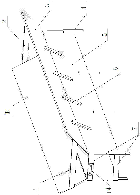
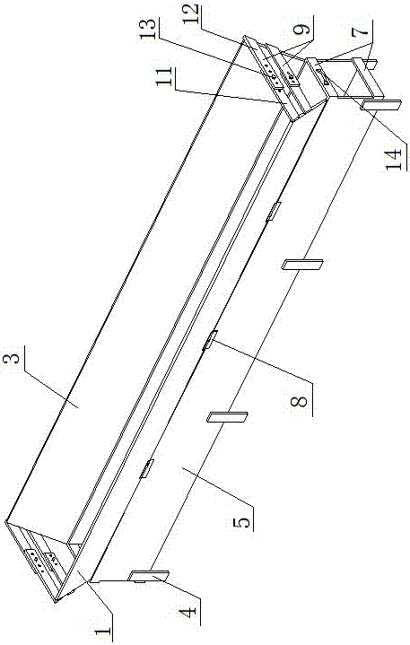
[0013] Such as figure 1 Shown embodiment 1, present embodiment comprises two vertical formworks 5, two oblique formworks 1,3, two groups of every group two (also can be three, four etc.) fixed and fastened form columns 7 (also But two fastening formworks), two groups of every group one (also can be two, three etc.) fixed tension formwork 2. The lower openings of the two vertical formworks 5 match the concrete entrances of the pouring wall formwork, and are clamped and fixed on the concrete entrance of the pouring wall formwork. The oblique template 3 at the operating end and the vertical template 5 below it are fixed on the upper end of the vertical template 5 at an angle of 30-45°, and the oblique template 1 at the other end and the vertical template 5 below it are fixed at an angle of 45-60°. Be fixed on this vertical template 5 upper ends....


PUM


Abstract

The invention discloses a receiving device for conveying concrete. The outlet formed by two vertical formworks is matched with an inlet for pouring the concrete of a wall formwork; a slanting formwork at the operation end and the corresponding vertical formwork under the slanting formwork are fixed or hinged to the upper end of the vertical formwork at the 30-45-degree angle, and a slanting formwork at the other end and the corresponding vertical formwork under the slanting formwork are fixed or hinged to the upper end of the vertical formwork at the 45-60-degree angle; fixing and fastening formwork columns or fastening formworks are symmetrically fixed to the two end surfaces of each vertical formwork respectively; the two ends of each fixing and tensioning formwork or adjustable tensioning formwork are fixed to the two end surface of each slanting formwork respectively. When a parapet wall is concreted by means of the receiving device, the consumption of the pouring concrete mixture is reduced, it is avoided that the poured concrete mixture is splashed outwards or scattered from the two sides of the parapet wall, the speed at which the concrete mixture is conveyed is unloaded, so that the concrete slowly flows into a parapet wall formwork, and the concrete stacked before vibration is stored.

Description

technical field [0001] The invention belongs to the field of building construction and relates to a material receiving device for conveying concrete into a formwork used for pouring parapet walls. Background technique [0002] Now the delivery of concrete at various construction sites mostly adopts the pumping method, and directly uses pump pipes to pour concrete on the wall column beams and slabs and other components that have supported the formwork, and the same is true for the delivery and pouring of parapet walls. In terms of whether all the concrete can enter the components smoothly, this method of direct pouring with pump pipes does not have a great impact on beams and slabs with large areas, but it has a great impact on narrow-section components such as parapet walls. Since the diameter of the pump pipe is larger than the width of the parapet wall, the conveyed and poured concrete cannot be completely transported into the parapet formwork and is scattered on both side...

Claims


Application Information

Patent Timeline
Patent Type & Authority Applications(China)
IPC IPC(8): E04G21/02
CPCE04G21/02
Inventor 展朝飞孙旭东王鹏宋喜艳贾泽鹏罗登科贺印印
Owner HEBEI CONSTR GRP CO LTD
Why Eureka
Try Eureka