
Fixed-shaft type lubricating-sealing mechanism of rotary shaft

A sealing mechanism and fixed shaft technology, which is applied in the direction of engine sealing, mechanical equipment, engine components, etc., can solve the problems of the sealing mechanism lacking lubrication mechanism, affecting the service life of the rotating shaft, and not being able to limit the position well, so as to achieve the sealing effect Good, easy to replace regularly, good locking effect

Inactive Publication Date: 2017-11-24
陈琦
View PDF0 Cites 1 Cited by
  • Summary
  • Abstract
  • Description
  • Claims
  • Application Information

AI Technical Summary

Problems solved by technology

The existing rotating shaft sealing mechanism only has a certain sealing effect. It is sleeved on the rotating shaft and cannot be well limited when rotating, resulting in the sealing mechanism shaking back and forth or even sliding relative to the rotating shaft, and the stability is poor; and the existing The sealing mechanism lacks the necessary lubricating mechanism, which leads to serious wear and tear of the rotating shaft after a period of use, which affects the service life of the rotating shaft; it is inconvenient to disassemble and assemble, and lacks the necessary stop mechanism when the rotating shaft is not driven

Method used


Image

  • Fixed-shaft type lubricating-sealing mechanism of rotary shaft

Examples


Embodiment Construction

[0019] The following will clearly and completely describe the technical solutions in the embodiments of the present invention with reference to the accompanying drawings in the embodiments of the present invention. Obviously, the described embodiments are only some, not all, embodiments of the present invention. Based on the embodiments of the present invention, all other embodiments obtained by persons of ordinary skill in the art without making creative efforts belong to the protection scope of the present invention.

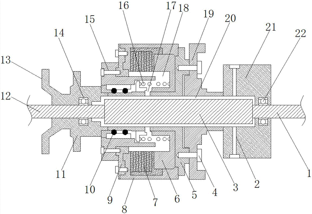
[0020] see figure 1 , in an embodiment of the present invention, a shaft-fixed lubricating and sealing mechanism for a rotating shaft includes a spacer shaft 3, an oil tank cover 8, a front seal cover 11, a fixed cover 19, and a rear seal cover 21, and the spacer shaft 3. The transmission shaft 12 is welded at the front end, and the drive shaft 1 is welded at the rear end of the distance shaft 3. The distance shaft 3, the transmission shaft 12 and the drive sh...


PUM


Abstract

The invention discloses a shaft-fixed lubricating and sealing mechanism for a rotating shaft, which comprises a fixed-distance shaft, an oil tank cover, a front sealing cover, a fixed cover and a rear sealing cover. The front end of the fixed-distance shaft is welded with a transmission shaft. The rear end of the shaft is welded with a drive shaft, and the outer part of the transmission shaft is provided with a front sealing cover; the rear end of the front sealing cover is connected to the front fuel tank cover through the front bolt, and the front fuel tank cover is connected to the fuel tank cover through screws. The rear end of the oil tank cover is connected to the rear oil tank cover; the diameter of the distance shaft is larger than that of the transmission shaft and the drive shaft, and the distance shaft is installed in the lubricating oil chamber, which effectively limits the position of the distance shaft to prevent the When the distance shaft rotates, it shakes back and forth, which improves the stability of its rotation. The lubricating oil in the oil guide chamber is conveniently injected into the lubricating oil chamber, which effectively lubricates the rotation of the distance shaft, reduces the wear of the distance shaft, and facilitates the maintenance of the oil tank cover. The assembly and disassembly of the shell is convenient for regular replacement of lubricating oil; the sealing effect is good, and it has a good locking effect.

Description

technical field [0001] The invention relates to the technical field of rotary shaft sealing machinery, in particular to a shaft-fixed lubricating and sealing mechanism for a rotary shaft. Background technique [0002] The sealing structure of the rotating shaft is a component that prevents foreign impurities from entering the inside of the rotating shaft during the use of the rotating shaft, and plays a good guiding role when the rotating shaft rotates. The existing rotating shaft sealing mechanism only has a certain sealing effect. It is sleeved on the rotating shaft and cannot be well limited when rotating, resulting in the sealing mechanism shaking back and forth or even sliding relative to the rotating shaft, and the stability is poor; and the existing The sealing mechanism lacks the necessary lubricating mechanism, resulting in serious wear and tear of the rotating shaft after a period of use, which affects the service life of the rotating shaft; disassembly and assembl...

Claims


Application Information

Patent Timeline
Patent Type & Authority Applications(China)
IPC IPC(8): F16J15/16
CPCF16J15/162
Inventor 陈琦
Owner 陈琦
Learn More