Electrical equipment winding length wireless detection device and detection method

A technology of electrical equipment and wireless detection, which is applied in the direction of measuring devices, mechanical measuring devices, and mechanical devices, etc., can solve the problems of large floor area, numerous equipment, and infeasible cable transmission, so as to avoid slipping and reduce slipping The effect of probability

Inactive Publication Date: 2017-11-24
SHENYANG INST OF AUTOMATION - CHINESE ACAD OF SCI
View PDF5 Cites 3 Cited by
  • Summary
  • Abstract
  • Description
  • Claims
  • Application Information

AI Technical Summary

Problems solved by technology

[0004] In addition, the existing detection method for coil length has not yet realized the remote transmission of detection data, and the problems of numerous equipment and large floor area in the electrical equipment production workshop make cable transmission unfeasible

Method used


Image

  • Electrical equipment winding length wireless detection device and detection method
  • Electrical equipment winding length wireless detection device and detection method
  • Electrical equipment winding length wireless detection device and detection method

Examples


Embodiment 1

[0056] In this embodiment, the detection device is a photoelectric encoder 14 .

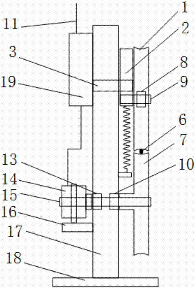
[0057] Such as figure 2 As shown, the photoelectric encoder 14 is arranged on the side of the main equipment support 17 away from the detection guide wheel 7, and the hollow shaft of the photoelectric encoder 14 is coaxially arranged with the detection guide wheel 7 and follows the detection guide wheel 7 Rotate, the photoelectric encoder bracket 16 is arranged on the main equipment bracket 17, and the photoelectric encoder 14 is installed on the photoelectric encoder bracket 16.

[0058] In this embodiment, the photoelectric encoder adopts Rip Avago's ZKP3808 photoelectric encoder.

[0059] The working principle of this embodiment is:

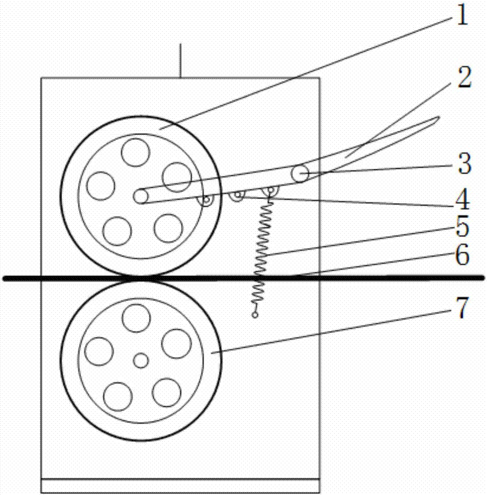
[0060] When the mechanism is working, press down the pinch wheel lever 2 to lift the pinch wheel 1, place the measured enameled wire 6 between the pinch wheel 1 and the detection guide wheel 7, and then put down the pinch wheel lever 2 to make the pinch wheel ...

Embodiment 2

[0066] In this embodiment, the detection device is a proximity switch 12 .

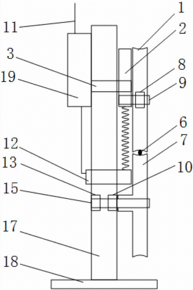
[0067] Such as image 3 As shown, the proximity switch 12 is fixedly mounted on the main equipment bracket 17, and a round hole for triggering the proximity switch 12 is provided on the detection guide wheel 7. When the position facing the front of the proximity switch 12 is a round hole, a high level is output. When the proximity switch 12 is blocked by the detection guide wheel 7, it outputs a low level. In this embodiment, five circular holes are provided on the detection guide wheel 7 .

[0068] In this embodiment, the model of the proximity switch 12 is PR08-1.5DN, and the manufacturer is Autonics.

[0069] The working principle of this embodiment is:

[0070] When the mechanism is working, press the compression lever 2 to lift the compression wheel 1, place the measured enameled wire 6 between the compression wheel 1 and the detection guide wheel 7, and then lower the compression wheel lever ...


PUM


Abstract

The invention relates to the field of electrical equipment detection, and particularly provides an electrical equipment winding length wireless detection device and detection method. The device comprises a pressing wheel, a pressing wheel lever, a pressing spring, a detection guide wheel, a detection device, a main equipment support and a data processing circuit board. The pressing wheel lever is hinged on the main equipment support. The pressing wheel is installed on the end part of the pressing wheel lever. The detection guide wheel is installed on the main equipment support and arranged below the pressing wheel. Multiple pressing spring hook position holes are arranged on the lower side of the pressing wheel lever. One end of the pressing spring is hooked on the main equipment support, and the other end is hooked on any pressing spring hook position hole. The main equipment support is provided with the detection device used for detecting the rotating angle of the detection guide wheel. The detection device is connected with the data processing circuit board. The length of the enameled wire can be accurately detected according to the process requirements and the length detection data can be transmitted through a wireless communication mode.

Description

technical field [0001] The invention relates to the field of electrical equipment detection, in particular to a wireless detection device and detection method for the winding length of electrical equipment. Background technique [0002] Electrical equipment (generators, motors, transformers, electric welding machines, etc.) are widely used in industrial production and daily life, and their essence is that enameled wires with different parameters are wound into coils of different shapes and specifications according to application requirements, and then threaded It is made of supporting parts such as iron core. Coil length detection is a necessary process for the factory inspection of electrical equipment. It is of great guiding significance for calculating the degree of consistency of product process parameters, counting equipment production capacity, and reducing corner waste. It also provides information support for subsequent production processes. [0003] Due to the diff...

Claims


Application Information

Patent Timeline
Patent Type & Authority Applications(China)
IPC IPC(8): G01B5/02G01B11/02G08C17/02
CPCG01B5/02G01B11/02G08C17/02
Inventor 彭士伟梁炜张晓玲于海斌李世明夏晔赵有健徐石明
Owner SHENYANG INST OF AUTOMATION - CHINESE ACAD OF SCI
Why Eureka
Try Eureka